
Shaft with a key system plays a vital role in transmitting power and torque in mechanical engineering. Key, keyway, and keyseat are the key structures that connect shafts to other parts. The existence of keyways enables shafts to work closely with parts such as gears and pulleys to achieve smooth and efficient power transmission. If the keyway is not designed accurately, it may cause loose connections, vibration, and noise during operation, and even cause equipment failure in severe cases, affecting normal production. Therefore, understanding the standard size, tolerance, and design dimension calculation of the keyway of the shaft is the basis for designing keyways and keyseats that can ensure the reliable operation of a mechanical project. In this guide, we are going to learn about the keyway and key of the shaft!
What is Key, Keyway, Keyseat & How They Work in Mechanical Engineering?
In mechanical engineering, a key connection is a common mechanical connection method, mainly used to fix shafts and hubs (such as gears, pulleys, couplings, etc.) together to transmit torque. Key connection is achieved by slotting the shaft and hub and inserting a component called a key. It can be said that keys and keyways are the most common form of fit in mechanical manufacturing. They are usually used to connect two or more parts so that they can rotate, drag, or perform other forms of movement.
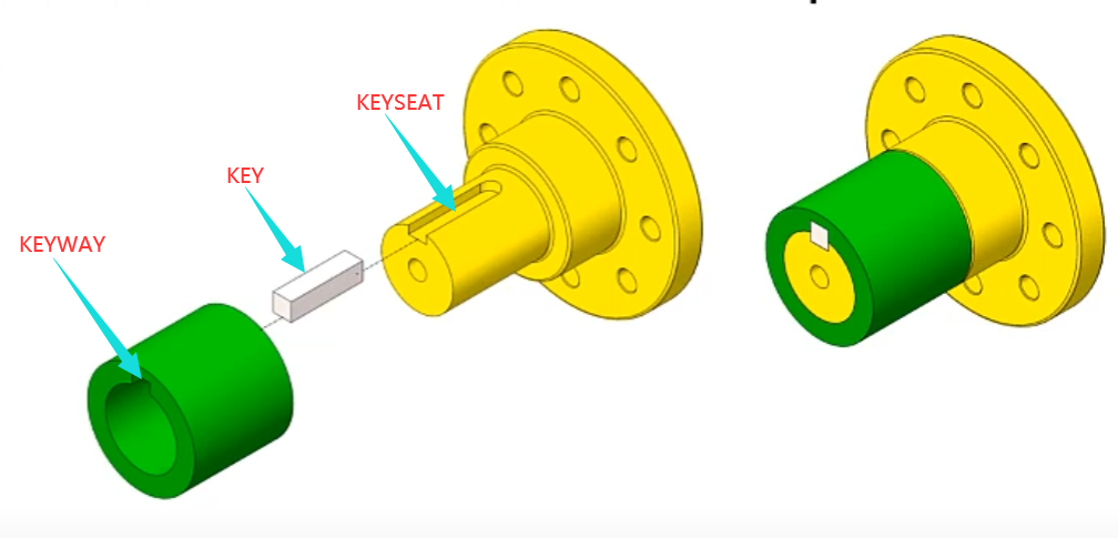
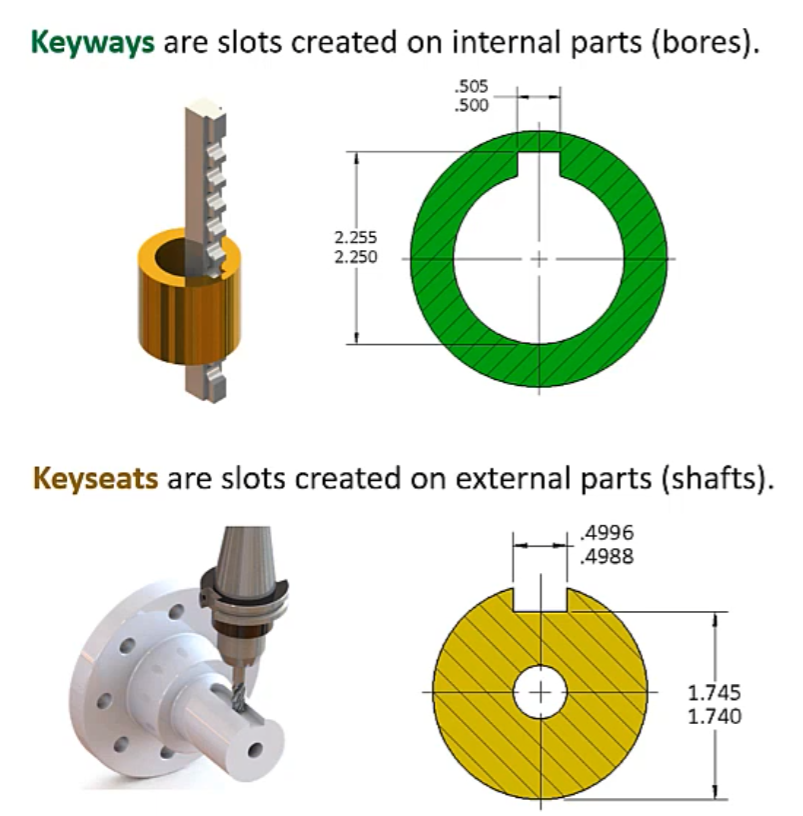
A key is a small, rigid machine element usually made of metal that fits into a groove keyway or key seat machined into both a rotating shaft and a mating hub or component like a gear, pulley, or coupling. Its primary purpose is to transmit torque from the shaft to the hub or vice versa, preventing relative rotation between the two components. When in use, one part of the key is embedded in the shaft, and the other part is embedded in the keyway of the hub (bore), which either ensures orientation or restricts rotational movement between parts. Keyways are the slot or groove cut on the internal cylindrical part (bore or hub), and keyseats are the slot or groove cut on the external part (shaft). In simple, keyseats and keyways are used for placing shaft keys and fixing the relative position of the shaft and the engaging part so that they rotate together to achieve the purpose of transmitting power and torque, and typically, they are both collectively called the keyway. Keyways will typically have their depth, width, and location specified, so as to give the full size and location of where the cut is to be made.
Shaft Keyway Types
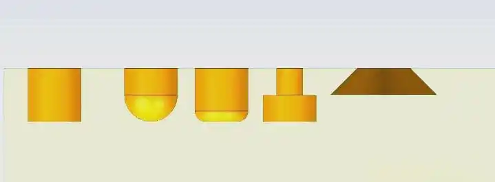
Parallel Keyway
Parallel keyways are a common standard shaft keyway, typically used to transmit small torque. Their main characteristic is a flat groove, where the keyway’s length and width are equal, often forming a square slot. The advantage of flat keyways is simple manufacturing and low cost. However, their load capacity is relatively low and unsuitable for high-torque applications. They are widely used due to their simple structure and ease of assembly/disassembly.
Woodruff Keyway
Woodruff keyways are commonly used standard shaft keyways, typically designed for transmitting larger torque. Their main feature is an arc-shaped groove, with a radius usually equal to 1/8 or 1/6 of the shaft diameter. Keyway length is twice its width. These keyways have high strength and load capacity, suitable for high-torque applications.
Taper Keyway
Tapered keyways have a trapezoidal or slanted cross-section with an inclined angle. They are typically used in high-speed, low-torque transmissions requiring high precision, low noise, and smooth operation. Their advantages are high transmission efficiency and smooth operation. However, they are more difficult to manufacture and install.
Gib-Head Keyway
Gib-Head keyways have a trapezoidal cross-section and are suitable for high-speed, low-torque transmissions where high transmission accuracy is required. They offer high efficiency and smooth operation, but the structure is complex and harder to machine.
Spline Keyway
Spline keyways consist of multiple slots and are typically used to connect two shafts and transmit rotational force. They are often fan-shaped, with the number and shape of slots varying as needed. Spline keyways are suitable for applications requiring higher transmission efficiency and greater torque capacity, such as high-speed shafts and high-torque rotating devices.
Standard Keyway Dimensions and Tolerances
The dimensions of keyways on both the hub and shaft are identical, and their width tolerances correspond with the key’s width tolerance. Generally, the basic dimension of a keyway width matches the selected key width, but with different tolerances. For example, under the common basic shaft system, the shaft keyway width tolerance band is h9.
The depth of the keyway is also strictly specified. For Type A keyways, depth t1 varies according to shaft diameter. For example:
- When shaft diameter d = 18–20 mm, t1 = 11 mm
- When d = 22–30 mm, t1 = 14 mm
The hub keyway depth t2 also has its own standard, which aligns with the shaft keyway depth to ensure proper key installation and secure connection.
Standard Keyway Design Dimension Parameters
To design a perfect keyway for your mechanical project, the following critical dimensions are involved:
When it comes to designing the perfect keyway for your mechanical project, the following key dimensions are involved:
- 1. Key Size (Width × Height) – Determined by shaft diameter using standard tables (e.g., ANSI, Machinery’s Handbook). For square keys, width = height. Example: For a 1″ shaft, use a ¼” × ¼” key.
- 2. Keyway Depth in Shaft (Dimension S) – Measured from the shaft outer diameter (OD) to the bottom of the keyway. Do not dimension by subtracting half the key height. Example: For a ¼” square key, S ≈ 0.859″ from shaft OD.
- 3. Keyseat Depth in Hub (Dimension T) – Measured from the hub inner diameter (ID) to the bottom of the keyseat. Example: For a ¼” square key, T ≈ 1.140″ from hub ID.
- 4. Keyway and Keyseat Width – Same as the key width. Important for ensuring proper fit and torque transmission.
- 5. Keyway Radius (Corner Fillet Radius) – Radius at the bottom corners of the keyway to reduce stress concentration. Typically 1/64″ to 1/32″ for small keys, should match the key’s edge radius or chamfer.
- 6. Keyway Width Tolerance – The keyway width tolerance controls the allowable variation in the width, and for a ¼” key, a common tolerance is +0.002″ / -0.000″ to allow proper fit.
- 7. Shaft Keyway Depth Tolerance – The tolerance for the shaft keyway depth (Dimension S) is often +0.000″ / -0.015″, ensuring the key fits tightly without excessive play.
- 8. Hub Keyseat Depth Tolerance – The tolerance for the hub keyseat depth (Dimension T) is typically +0.010″ / -0.000″, which helps ensure easy assembly and proper fit.
- 9. Keyway Length – The keyway length is the axial length of the slot along the shaft or hub, and it should match or slightly exceed the length of the key to provide full engagement.
- 10. Shaft Diameter – The shaft diameter is the nominal size of the shaft, and it determines the appropriate key size (e.g., a 1″ shaft calls for a ¼” × ¼” key).
- 11. Hub Bore Diameter – The hub bore diameter is the nominal size of the hole in the hub, and it should match the shaft diameter to ensure a proper press or slip fit, depending on the application.
Below, we’ve sorted out the standard keyway size chart for metric and imperial to provide a convenient dimension query for transmission mechanism design. You can quickly check keyway dimensions such as shaft diameter, key width, key height, shaft keyway depth, hub keyseat depth, and tolerances to help your design work.
Metric Standard Key & Keyway Size Chart in MM
| Shaft Ø Over | Shaft Ø Thru | Key Size Nominal | Keyway Width Tolerance (mm) | Keyway Depth “T2” Hub (mm) | Keyway Radius “R” (mm) | |||||
|---|---|---|---|---|---|---|---|---|---|---|
| Width W | Height H | JS9 | P9 | D10 | Min | Max | Min | Max | ||
| 6 | 8 | 2 | 2 | ±0.0125 | −0.031/−0.006 | +0.020/+0.060 | 1.0 | 1.1 | 0.08 | 0.16 |
| 8 | 10 | 3 | 3 | ±0.0125 | −0.031/−0.006 | +0.020/+0.060 | 1.4 | 1.5 | 0.08 | 0.16 |
| 10 | 12 | 4 | 4 | ±0.0150 | −0.042/−0.012 | +0.030/+0.078 | 1.8 | 1.9 | 0.08 | 0.16 |
| 12 | 17 | 5 | 5 | ±0.0150 | −0.042/−0.012 | +0.030/+0.078 | 2.3 | 2.4 | 0.16 | 0.25 |
| 17 | 22 | 6 | 6 | ±0.0150 | −0.042/−0.012 | +0.030/+0.078 | 2.8 | 2.9 | 0.16 | 0.25 |
| 22 | 30 | 8 | 7 | ±0.0180 | −0.051/−0.015 | +0.040/+0.098 | 3.3 | 3.5 | 0.16 | 0.25 |
| 30 | 38 | 10 | 8 | ±0.0180 | −0.061/−0.018 | +0.040/+0.098 | 3.3 | 3.5 | 0.25 | 0.40 |
| 38 | 44 | 12 | 8 | ±0.0215 | −0.061/−0.018 | +0.050/+0.120 | 3.3 | 3.5 | 0.25 | 0.40 |
| 44 | 50 | 14 | 9 | ±0.0215 | −0.061/−0.018 | +0.050/+0.120 | 3.8 | 4.0 | 0.25 | 0.40 |
| 50 | 58 | 16 | 10 | ±0.0215 | −0.061/−0.018 | +0.050/+0.120 | 4.3 | 4.5 | 0.25 | 0.40 |
| 58 | 65 | 18 | 11 | ±0.0215 | −0.061/−0.018 | +0.050/+0.120 | 4.4 | 4.6 | 0.25 | 0.40 |
| 65 | 75 | 20 | 12 | ±0.0260 | −0.074/−0.022 | +0.065/+0.149 | 4.9 | 5.1 | 0.40 | 0.60 |
| 75 | 85 | 22 | 14 | ±0.0260 | −0.074/−0.022 | +0.065/+0.149 | 5.4 | 5.6 | 0.40 | 0.60 |
| 85 | 95 | 25 | 14 | ±0.0260 | −0.074/−0.022 | +0.065/+0.149 | 5.4 | 5.6 | 0.40 | 0.60 |
| 95 | 110 | 28 | 16 | ±0.0260 | −0.074/−0.022 | +0.065/+0.149 | 6.4 | 6.6 | 0.40 | 0.60 |
| 110 | 130 | 32 | 18 | ±0.0310 | −0.088/−0.026 | +0.080/+0.180 | 7.4 | 7.6 | 0.40 | 0.60 |
| 130 | 150 | 36 | 20 | ±0.0310 | −0.088/−0.026 | +0.080/+0.180 | 8.4 | 8.7 | 0.70 | 1.00 |
| 150 | 170 | 40 | 22 | ±0.0310 | −0.088/−0.026 | +0.080/+0.180 | 9.4 | 9.7 | 0.70 | 1.00 |
| 170 | 200 | 45 | 25 | ±0.0310 | −0.088/−0.026 | +0.080/+0.180 | 10.4 | 10.7 | 0.70 | 1.00 |
| 200 | 230 | 50 | 28 | ±0.0310 | −0.088/−0.026 | +0.080/+0.180 | 11.4 | 11.7 | 0.70 | 1.00 |
| 230 | 260 | 56 | 32 | ±0.0370 | −0.106/−0.032 | +0.100/+0.220 | 12.4 | 12.7 | 1.20 | 1.60 |
| 260 | 290 | 63 | 32 | ±0.0370 | −0.106/−0.032 | +0.100/+0.220 | 12.4 | 12.7 | 1.20 | 1.60 |
| 290 | 330 | 70 | 36 | ±0.0370 | −0.106/−0.032 | +0.100/+0.220 | 14.4 | 14.7 | 1.20 | 1.60 |
| 330 | 380 | 80 | 40 | ±0.0370 | −0.106/−0.032 | +0.100/+0.220 | 15.4 | 15.7 | 2.00 | 2.50 |
| 380 | 440 | 90 | 45 | ±0.0435 | −0.124/−0.037 | +0.120/+0.260 | 17.4 | 17.7 | 2.00 | 2.50 |
| 440 | 500 | 100 | 50 | ±0.0435 | −0.124/−0.037 | +0.120/+0.260 | 19.5 | 19.8 | 2.00 | 2.50 |
Imperial Standard Key & Keyway Size Chart in Inches
| Shaft Dia Over | Shaft Dia To (Incl) | Key Size (Width × Height) | Keyway Geometry (inches) | Class 1 Fit (Parallel Key) | Class 2 Fit (Parallel/Taper) | ||||||||||
|---|---|---|---|---|---|---|---|---|---|---|---|---|---|---|---|
| A | B | C | D | E | F | R | Width Tol | Shaft Depth | Hub Depth | Width Tol | Shaft Depth | Hub Depth | |||
| 1/4″ | 1/2″ | 1/8″×1/8″ | 0.125 | 0.078 | 0.126 | 0.066 | 0.125 | 0.125 | 0.010 | +0.002/0.000 | +0.000/−0.015 | +0.010/0.000 | +0.002/0.000 | +0.000/−0.015 | +0.010/0.000 |
| 1/2″ | 3/4″ | 3/16″×3/16″ | 0.188 | 0.113 | 0.189 | 0.094 | 0.188 | 0.188 | 0.010 | +0.002/0.000 | +0.000/−0.015 | +0.010/0.000 | +0.002/0.000 | +0.000/−0.015 | +0.010/0.000 |
| 3/4″ | 1″ | 1/4″×1/4″ | 0.250 | 0.148 | 0.251 | 0.121 | 0.250 | 0.252 | 0.010 | +0.003/0.000 | +0.000/−0.015 | +0.010/0.000 | +0.003/0.000 | +0.000/−0.015 | +0.010/0.000 |
| 1″ | 1 1/4″ | 5/16″×5/16″ | 0.313 | 0.183 | 0.313 | 0.148 | 0.312 | 0.314 | 0.010 | +0.004/0.000 | +0.000/−0.015 | +0.010/0.000 | +0.002/0.000 | +0.000/−0.015 | +0.010/0.000 |
| 1 1/4″ | 1 1/2″ | 3/8″×3/8″ | 0.375 | 0.219 | 0.376 | 0.175 | 0.375 | 0.377 | 0.015 | +0.004/0.000 | +0.000/−0.015 | +0.010/0.000 | +0.002/0.000 | +0.000/−0.015 | +0.010/0.000 |
| 1 1/2″ | 2″ | 1/2″×1/2″ | 0.500 | 0.289 | 0.501 | 0.230 | 0.500 | 0.502 | 0.020 | +0.004/0.000 | +0.000/−0.015 | +0.010/0.000 | +0.002/0.000 | +0.000/−0.015 | +0.010/0.000 |
| 2″ | 2 1/2″ | 5/8″×5/8″ | 0.625 | 0.354 | 0.625 | 0.278 | 0.627 | 0.627 | 0.020 | +0.004/0.000 | +0.000/−0.015 | +0.010/0.000 | +0.002/0.000 | +0.000/−0.015 | +0.010/0.000 |
| 2 1/2″ | 3″ | 3/4″×3/4″ | 0.750 | 0.430 | 0.751 | 0.339 | 0.750 | 0.750 | 0.020 | +0.004/0.000 | +0.000/−0.015 | +0.010/0.000 | +0.002/0.000 | +0.000/−0.015 | +0.010/0.000 |
| 3″ | 3 1/2″ | 7/8″×7/8″ | 0.875 | 0.501 | 0.876 | 0.393 | 0.875 | 0.877 | 0.062 | +0.005/0.000 | +0.000/−0.015 | +0.010/0.000 | +0.002/0.000 | +0.000/−0.015 | +0.010/0.000 |
| 3 1/2″ | 4″ | 1″×1″ | 1.000 | 0.572 | 1.001 | 0.448 | 1.000 | 1.003 | 0.062 | +0.005/0.000 | +0.000/−0.015 | +0.010/0.000 | +0.002/0.000 | +0.000/−0.015 | +0.010/0.000 |
All dimensions in inches
CL = Clearance fit; INT = Interference fit
Data sourced from ANSI B17.1 and BS 46:1958
* indicates non-standard key size (omitted for clarity)
How to Determine the Keyway Dimensions?
To determine keyway dimensions correctly, it’s important to follow a step-by-step method, referring to standard tables. Let’s walk through an example where we are designing for a 1-inch shaft and a 1-inch bore.
Step 1: Determine the Key Size
Start by looking at the first table, which lists nominal shaft diameters. You won’t find an exact “1-inch shaft” listed, but you will find a range. For a 1-inch shaft, it falls within the range “over 7/8″ and up to 1-1/4”. According to the table, this range uses a 1/4-inch wide key.
Also, note the style of key recommended. At the bottom of the chart, it states:
“Square keys are preferred for shaft diameters above this heavy line.”
So, for our example, we’ll use a 1/4″ x 1/4″ square key.
Step 2: Determine the Keyway Depth
Now go to the next table to find the keyway depth. This table is based on shaft diameter, not key size.
For the shaft keyway, look for Dimension S (this represents the depth in the shaft).
For the hub keyway, look for Dimension T (this is the depth in the hub).
For a 1-inch shaft and 1/4″ square key:
- S (shaft depth) = 0.859 inches
- T (hub depth) = 1.14 inches
Step 3: Apply the Correct Tolerances
Now move to the tolerance table, often labeled Table 4 in the Machinery’s Handbook.
For keyway width (side to side), we are now looking at key size, not shaft size.
For a key width up to 1/2 inch, the keyway width tolerance is:
- +0.002 / -0.000 inches
For depth tolerances:
- Shaft keyway (Dimension S): +0.000 / -0.015 inches
- Hub keyway (Dimension T): +0.010 / -0.000 inches
These tolerances are important for ensuring the key fits properly and functions reliably without excessive play or stress.
How To Calculate Keyway Dimensions – Depth & Width Formula
Proper dimensioning is important to avoid costly manufacturing errors. A real-world case involved incorrect measurement from the shaft top to the keyway bottom, resulting in thousands of dollars in unusable parts. Always dimension:
- From shaft OD to keyway bottom
- From hub ID to keyseat bottom
Keyway Width & Depth Calculation Formulas
Slot width and depth are often needed in engineering design and manufacturing, especially in machining and industrial production. These formulas help engineers determine accurate keyway dimensions:
For circular keyways:
- Slot Width = (Outer Diameter – Inner Diameter) / 2
- Slot Depth = Outer Diameter – Inner Diameter
For square or rectangular keyways:
- Slot Width = (Outer Side Length – Inner Side Length) / 2
- Slot Depth = Outer Side Length – Inner Side Length
These formulas may vary depending on groove shapes and part requirements. Engineers must adjust them accordingly for specific applications like bearing housings, rectangular grooves, or trapezoidal grooves.