
Engineering drawings are a universal language in CNC machining and mechanical manufacturing. These technical documents are important in communicating how parts are to be made, assembled, and checked, ensuring that every detail is clearly understood by engineers, machinists, and inspectors alike. However, for those new to the field, making sense of the countless symbols and abbreviations on a drawing can be a challenge. Here, we present this practical guide to the Engineering Drawing abbreviations and symbols, with meaning explained and their significance in technical and CNC machining drawings.
What are Engineering Drawing Abbreviations and Symbols?
Engineering drawing abbreviations and symbols are standardized shorthand notations and graphical representations used to convey design information quickly and unambiguously. Symbols represent features like holes, welds, surfaces, and shapes, while abbreviations often stand for common terms or instructions in technical specs. These conventions help summarize complex details in a concise manner, saving space and reducing potential misinterpretations.
The drawings themselves come in various types:
- Assembly drawings show how different components fit together and their functional relationships.
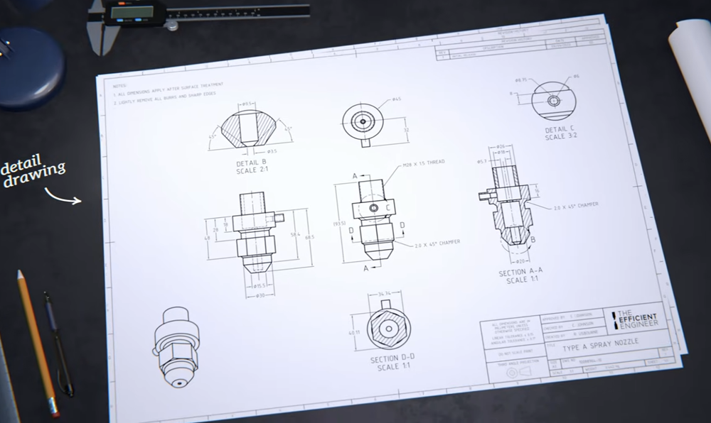
- Detail drawings define the geometry of individual components, providing all information needed for fabrication and inspection.
- Layout drawings illustrate design concepts without extensive detail.
- Interface control drawings specify how components interact with each other.
Most drawings follow standards such as ANSI Y14 or ISO, ensuring consistency across industries and regions, though companies may have their own specific requirements.
Why Engineering Drawing Symbols & Abbreviations are Important
The use of symbols and abbreviations is not just a matter of tradition; it is essential for clear, efficient communication. Technical drawings often serve as the primary means of communicating design intent between engineers, machinists, quality inspectors, and other stakeholders. Abbreviations and symbols enable teams to:
- Save space: They allow critical information to be included in a compact format, preventing clutter and reducing the risk of misinterpretation.
- Maintain consistency: Standardized symbols and abbreviations ensure everyone interprets the drawing in the same way, regardless of language or location.
- Speed up manufacturing: Quick reference to symbols and abbreviations helps machinists and engineers work efficiently, reducing the chances of errors or delays.
Without these standardized notations, technical drawings would become unwieldy and prone to miscommunication, leading to costly mistakes in design and manufacturing.
Engineering Drawing Symbols & Meaning
Mechanical engineering drawings use a range of symbols to represent features, geometric controls, and machining instructions. These symbols are essential for sharing precise requirements with CNC machinists and design engineers. Below is a comprehensive table listing common symbols, their meanings, and typical uses:
Common Engineering Drawing Symbols
| Symbol | Meaning (full form) | Uses in CNC/Technical Drawings |
|---|---|---|
| Φ | Diameter | Specifies the diameter of holes, shafts, etc. |
| R | Radius | Indicates the radius of arcs or fillets |
| SR | Spherical Radius | Used for spherical surfaces |
| SΦ | Spherical Diameter | For spherical features |
| t | Thickness | Shows thickness of a part or feature |
| EQS | Equally Spaced | Specifies uniform spacing (e.g., holes) |
| C | 45° Chamfer | Indicates a chamfered edge |
| □ | Square | Marks a square shape/feature |
| ⏐⏐ | Depth | Indicates depth of a drilled or milled feature |
| ⌵ | Countersink (CSK) | Shows a conical recess for screw heads |
| ⎾ | Counterbore | Indicates a cylindrical recess |
| ⌒ | Arc Length | Length of an arc |
| ∠ | Angle | Specifies angular dimensions |
| SD | Major Diameter | Used in threads, gear features |
| PD | Pitch Diameter | Threads and gears |
| LD | Minor Diameter | Threads |
| +/− | Plus/Minus Tolerance | Tolerance on dimensions |
| S | Feature Size | Identifies specific size of a feature |
| Q | Unfolded Length | Sheet metal development |
| A/B/C/D/E/F | Datum Reference | Specifies datums for geometric tolerances |
| CZ | Common Tolerance Zone | For features sharing a tolerance zone |
| SF | Spotface | Indicates a flat surface for bolt heads |
| E | Envelope Requirement | Maximum material boundary |
| R (inside circle) | Reversible Requirement | Centering or reversal tolerance |
| M | Maximum Material Condition | For geometric controls |
| L | Least Material Condition | For geometric controls |
| F | Free State | Unrestricted condition |
| U | Projected Tolerance Zone | Tolerance in a projected area |
Engineering Drawing Abbreviations & Meaning
Abbreviations are shorthand notations used to represent commonly used terms and instructions on technical drawings. They help to keep the drawing concise and readable while ensuring all necessary information is communicated. Below is a table of widely used abbreviations, their meanings, and typical applications:
| Abbreviation | Meaning (FULL FORM) | Typical Use/Context |
|---|---|---|
| CSK | Countersunk | Screw holes for flush fasteners |
| CBORE | Counterbore | Flat-bottomed holes for bolts |
| DRG | Drawing | Reference to the technical drawing |
| ASSY | Assembly | Refers to assembly drawings |
| A/F | Across Flats | Measurement for hex bolts/nuts |
| SK | Sketch | Preliminary or simplified drawing |
| SQ | Square | Indicates square features |
| DIM | Dimension | Refers to measured features |
| INT | Internal | Inside surfaces or features |
| EXT | External | Outside surfaces or features |
| HEX | Hexagonal | Six-sided feature or nut |
| ID | Inside Diameter | Internal diameter of a hole/cylinder |
| OD | Outside Diameter | External diameter |
| DP | Diametrical Pitch | Used in gears and threads |
| CYL | Cylinder | Cylindrical feature |
| FIG | Figure | Reference to a figure or illustration |
| GL | Ground Level | Elevation reference on site |
| LH | Left Hand | Thread or feature orientation |
| RH | Right Hand | Thread or feature orientation |
| TYP | Typical | Indicates repeated features |
| REF | Reference | For reference only, not for production |
| APPD | Approved | Approval status for design |
| AUX | Auxiliary | Auxiliary view or part |
Most Used Technical Drawing Abbreviations & Symbols: CSK, DRG, ASSY, A/F, SK, SQ Meaning
Some abbreviations and symbols appear so often in engineering drawings that every engineer, machinist, or technician must be familiar with them:
- CSK (Countersunk): Indicates that a hole is to be tapered, typically to allow a screw head to sit flush with or below the surface of the part. The CSK symbol or abbreviation is often accompanied by diameter and angle specifications.
- DRG (Drawing): Refers to the technical drawing itself, used in notes, references, or document control.
- ASSY (Assembly): Used to denote assembly drawings or assembly instructions, which show how multiple parts fit together.
- A/F (Across Flats): A measurement term commonly used for hexagonal features, such as nuts and bolts, to specify the distance between two parallel faces.
- SK (Sketch): Represents a simplified or preliminary drawing, often used in early design stages or for minor changes.
- SQ (Square): Used to specify that a feature (such as a hole or recess) must be square in shape, or to give a dimension for a square cross-section.
These abbreviations and symbols are not only prevalent in technical drawings but are also critical for ensuring that parts are manufactured and assembled as intended.
How To Read Engineering Drawing?
1. Recognizing the Purpose of Technical Drawings
In engineering, when an object is designed, a technical drawing is used to represent it graphically on a screen or sheet so that engineers, workers, and users can communicate with each other and see what it looks like. These drawings allow everyone involved to visualize the part or assembly before production begins.
2. Starting With the Title Block
The first thing to do to interpret a drawing is to read the title block. This is a table usually found in the lower right corner that contains all the primary information. It typically includes the company logo, the designer’s name (to know who to contact), a title code or drawing number, and anything else needed to identify and track the object. Usually in a separate area, the revision number and date show if it is the latest version of the drawing and when it was made. The title block also provides the scale and the paper size required for printing, making sure measurements and proportions are correct.
3. Understanding the Scale
The drawing of an object most times doesn’t have actual dimensions but is scaled to fit into the dimensions of a sheet. If the sheet is printed in the indicated format, then the scale will be correct. For example, a scale of 1:1 means the drawing is full size and matches the real object. If the scale is 1:2, this means the object is drawn at half its real size; measurements must be multiplied by two to get the true size. If the scale is 2:1, the object is drawn twice as large, so measured values should be divided by two.
4. Identifying Projection Methods
Another fundamental element is the symbol that defines which orthogonal projection is used: either first angle projection (the European standard) or third angle projection (the American standard). The orthogonal projections are not randomly arranged—they are aligned according to one of these two systems. With first angle projection, the object lies between the observer and the projection planes, and each view is projected onto the inner walls of a cube, which is then unfolded to display all views. In third angle projection, the projection planes are between the observer and the object, so each view is projected onto the outer walls of the cube.
5. Reading Views and Projections
Some projections are required to represent the object on a sheet of paper. There is often a three-dimensional representation, like an isometric axonometry, where the XYZ axes form three equal angles of 120°. To fully describe the object, three orthographic views are typically provided—front, top, and right. In total, there can be up to six two-dimensional images showing perpendicular perspectives of the object.
6. Checking Dimensions and Tolerances
General tolerance is also present in orthogonal projections. Dimensions are numerical values that show the real sizes of the object, and these are usually expressed in millimeters in mechanical drawings. Since absolute perfection isn’t expected in manufacturing, tolerance values are provided. For example, if a 41 mm dimension has a tolerance of ±0.10, a manufacturing error is acceptable between 41.1 mm and 40.9 mm. Tolerances can also be specific to certain dimensions. There are also undimensioned fillets and chamfers, which must be considered unless specified otherwise.
7. Recognizing Lines and Their Meanings
The drawing is made up of different lines of various thicknesses—continuous or dashed. Each line has a specific meaning. The thick line defines all the contours and edges visible in that view, while the dashed line shows those that are hidden. A dash-dot line indicates symmetry if the object on either side is mirrored. Dash-dot lines are also used for holes and for section views if there are arrows showing the viewing direction and letters that are referenced in the section drawing.
8. Using Section and Detail Views
A section is an internal view of the object, shown by crossed fields with 45° lines to represent the internal surface as if it were the cut surface of the solid. A detail is an enlargement of a certain area, always named by letters, where irregular lines interrupt the drawing, leaving only the necessary parts.
9. Understanding Dimensioning Practices
Dimensions are represented through thin continuous lines placed next to numerical values, indicating lengths of various parts of the object. Fillets are marked with the letter “R,” diameters with the symbol “Ø,” and chamfers with specified height and degree of inclination. These should always be arranged outside the projections and can be attached to visible lines or symmetry axes. They are placed internally only if necessary, and hidden lines are not dimensioned.
10. Reading Threaded Features and Fasteners
Threaded holes are shown as two concentric circles for the root and crest of the thread. Usually, threaded holes are defined according to the ISO standard, with abbreviations such as “M6” indicating the diameter of the hole and the thread. After an “X,” a fine thread may be shown, or if not present, coarse thread is assumed. After another “X,” the length of the threaded hole is given. Often, the hole has a countersink or counterbore to hold a screw head, specified with dimensions and standard to the screw type.
11. Interpreting Surface Finish, Material, and Notes
Additional lines may indicate surface finish, roughness, or other characteristics that cannot be drawn, such as the material. For example, acronyms from the AISI and SAE designation system may specify common 304 stainless steel. Surface roughness can be shown for a particular face and may differ from the general value. There may also be notes for machining processes or warnings.
12. Applying Drawing Knowledge
With these steps, you can use technical drawings to create an object or design a project. These principles can be used each time you review a technical drawing, guiding you from the drawing board to the finished product with accuracy.
If you found this guide useful, consider bookmarking it for future reference or sharing it with colleagues new to technical drawings. The more familiar your team becomes with these standards, the smoother your projects will run!