
Stress is defined as the intensity of internal forces within a solid material and is a fundamental concept in engineering mechanics. Normal stress, shear stress, and bearing stress are the three main components used to describe the internal force state of a body, as well as the way forces are applied. Let’s take a closer look at these different types of stresses in the strength of materials that develop within solid bodies, along with their roles in various load-carrying structures. In this blog, we will dig deeper into the differences and relationship between normal stress, shear stress, and bearing stress by detailing their definition, diagram, symbol, units, area, calculation equation (formula), and examples.
Normal Stress vs Shear Stress, Bearing Stress – Types of Stresses in Strength of Materials
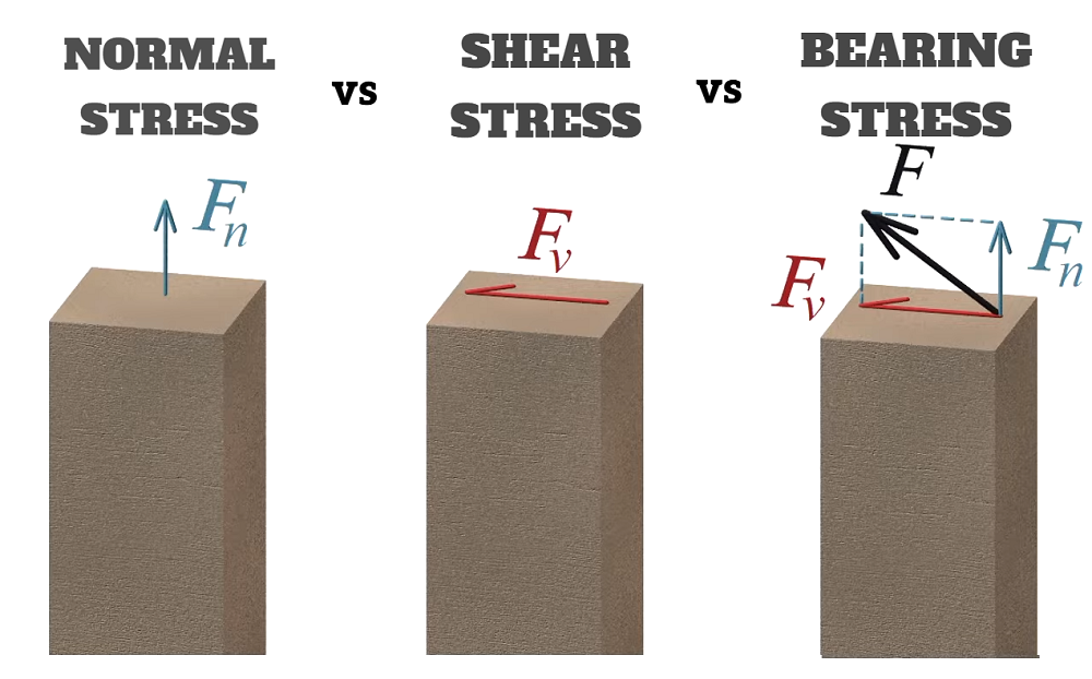
Stress in general is calculated as a force divided by area; any force acting on a section could be projected into a force perpendicular to a section and a force parallel to it. Materials typically show different strength levels depending on the direction of the force with respect to the cross-section area. To distinguish between these cases and describe stresses more accurately, two stress categories are defined as normal stress and shear stress. Bearing stress is not a separate stress category but is a special case of normal stress. So what are the differences and relations between these three types of stress in strength of materials?
Before discussing the differences between normal, shear, and bearing stress, let’s break down each of them individually:
1. What is Normal Stress?
Normal Stress Definition
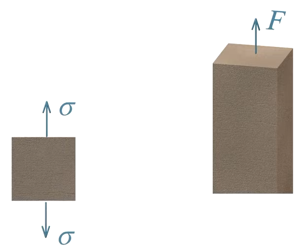
Normal stress is the intensity of force acting perpendicular to the cross-sectional area of a material. It develops inside a body when an axial load, either tension or compression, is applied at a right angle (90 degrees) to the area. This perpendicular action means normal stress can cause stretching (tensile stress) if the force pulls, or squeezing (compressive stress) if the force pushes. In both cases, the stress is uniformly distributed over the cross-section in idealized mechanics problems.
Normal Stress Symbol
The standard symbol for normal stress is the Greek letter σ (sigma).
Normal Stress Units
Normal stress is measured in units of force per unit area:
- In SI: Pascals (Pa), typically expressed as Megapascals (MPa) (1 MPa = 1,000,000 Pa)
- In imperial units: pounds per square inch (psi), or kips per square inch (ksi)
Normal Stress Area
The area used in normal stress calculations is the cross-sectional area perpendicular to the applied force. For a rod or bar, this is often a circular area (A = πd²/4), while for a rectangular section it is width times height (A = b × h).
Normal Stress Diagram
A typical diagram shows a member with a force applied along its axis and a cross-section exposed:
[Side View]
 ──────────────
|             |   ← Force P (tension or compression)
|             |
|             |
|             |
 ──────────────

[Cross-Section]
   ___________
  |           |
  |    area   |  ← Cross-section perpendicular to P
  |___________|
The normal force acts perpendicular to this area, causing stress throughout the section.
Normal Stress Formula & Equation – How To Calculate Normal Stress?
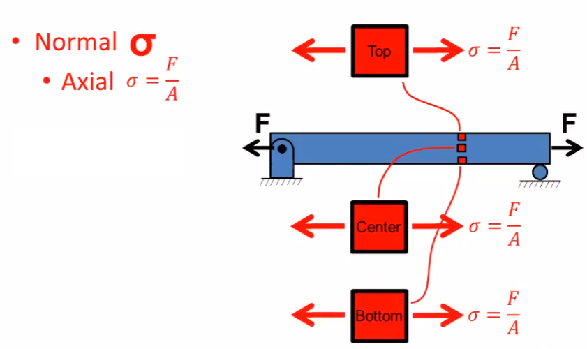
The basic equation for normal stress is:
σ = P / A
Where:
- σ = normal stress
- P = axial force (can be tensile or compressive)
- A = cross-sectional area perpendicular to the force
Maximum Normal Stress Formula
The maximum normal stress occurs at the location of the highest axial force and the smallest cross-sectional area:
σmax = Pmax / Amin
If the axial force and area are constant, the maximum and average values are the same.
Average Normal Stress Formula
For uniform loading and area:
σavg = P / A
This is the most commonly used formula in basic mechanics of materials for centric (axially aligned) loading.
Normal Stress Example
Example: Calculating Normal Stress in a Loaded Bar
Suppose a steel bar has a square cross-section measuring 50 mm × 50 mm and is subjected to a tensile force of 100 kN.
Step 1: Find the Cross-Sectional Area
- A = width × height = 50 mm × 50 mm = 2,500 mm²
Step 2: Calculate the Normal Stress
- σ = P / A = 100,000 N / 2,500 mm² = 40 N/mm²
To express in megapascals:
- 1 N/mm² = 1 MPa, so σ = 40 MPa
Interpretation:
This means the bar experiences a normal stress of 40 MPa throughout its cross-section under this load.
Additional Example: Variable Area and Force
If a rod has different sections with various diameters and is subjected to different axial forces:
- At a section with diameter = 1 in and force 3 kips (tension):
A = π(1 in)²/4 = 0.785 in²,
σ = 3 kips / 0.785 in² ≈ 3.82 ksi (tension) - At a section with diameter = 2 in and force -6 kips (compression):
A = π(2 in)²/4 = 3.14 in²,
σ = -6 kips / 3.14 in² ≈ -1.91 ksi (compression)
2. What is Shear Stress?
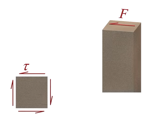
Shear Stress Definition
Shear stress is the internal force per unit area that acts parallel to the cross section of a material. This type of stress arises when forces are applied in such a way that they cause adjacent layers of a material to slide past one another. For example, in bolts, rivets, beams, or even when slicing bread or using scissors, shear stress is present where the force acts parallel to the surface, promoting a sliding action between different sections. Shear stress is different from normal stress, which acts perpendicular to a section, as it is associated with forces that attempt to tear or shear the material.
Shear Stress Symbol
Shear stress is commonly denoted by the Greek letter τ (tau).
Shear Stress Units
The units for shear stress are:
- Pascals (Pa) in the SI system, usually expressed as Megapascals (MPa), where 1 MPa = 1,000,000 Pa.
- Pounds per square inch (psi) in imperial units.
Shear Stress Area
The area used to calculate shear stress depends on the type of loading:
- For pins, bolts, or rods, the shear area is typically the cross-sectional area perpendicular to the force direction:
A = πr² for a circular section, where r is the radius. - In double shear connections, the area is multiplied by the number of shear planes.
Shear Stress Diagram
A simple shear stress diagram for a pin in single and double shear:
[Single Shear]
   -------------
  |   Plate    |
   -------------
      |   |
      |   |<-- Pin (shearing plane at one section)
      |   |

[Double Shear]
   -------------    -------------
  |   Plate    |----|   Plate    |
   -------------    -------------
        |   |<-- Pin (shearing planes at two sections)
        |   |
In each case, the shear force acts parallel to the cross-sectional area at the shearing plane(s).
Shear Stress Formula & Equation – How To Calculate Shear Stress?
Shear stress is calculated by dividing the applied force by the area over which the force acts:
τ = V / A
Where:
- τ = shear stress
- V = applied shear force
- A = area subject to shear
For double shear:
τ = V / (2A)
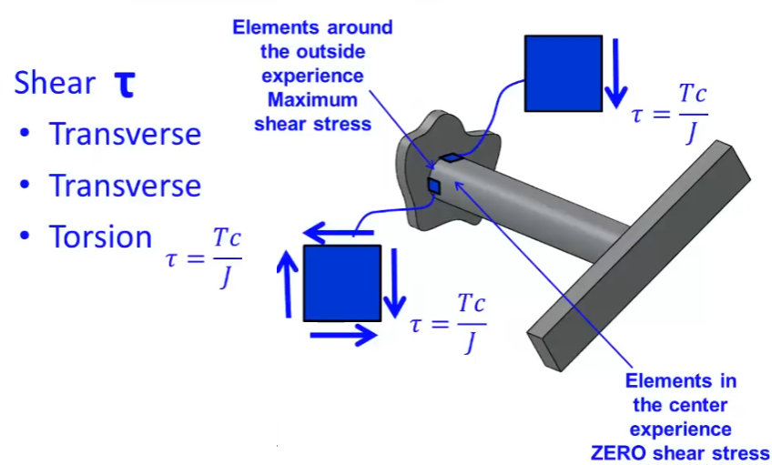
Maximum Shear Stress Formula
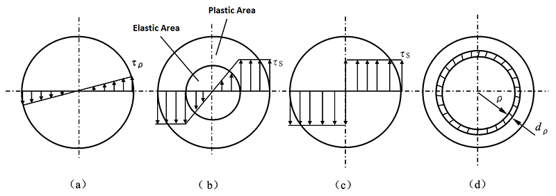
In many practical cases, the maximum shear stress in a cross-section (such as a rectangular or circular section) can be higher than the average value. For example, in a circular shaft under torsion, the maximum shear stress occurs at the outer surface:
τmax = Tc / J
Where:
- T = applied torque
- c = outer radius of the shaft
- J = polar moment of inertia
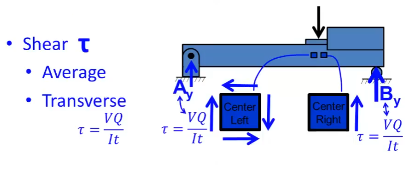
Transverse Shear Stress Formula
Transverse shear stress in beams subjected to transverse loading is given by:
τ = VQ / (Ib)
Where:
- V = internal shear force at the section
- Q = first moment of area above (or below) the point where the shear stress is being calculated
- I = second moment of area (moment of inertia) about the neutral axis
- b = width of the beam at the point of interest
Torsional Shear Stress Formula
For a solid circular shaft under torsion:
τ = T*r / J
Where:
- T = torque applied to the shaft
- r = distance from the center to the point of interest (maximum at the outer surface)
- J = polar moment of inertia (J = π d⁴ / 32 for a solid circular shaft)
For a hollow shaft:
J = π (douter⁴ – dinner⁴) / 32
Average Shear Stress Formula
The average shear stress is calculated as:
τavg = V / A
Where:
- V = applied shear force
- A = area over which the force acts
For double shear:
τavg = V / (2A)
Shear Stress Example
Example: Shear Stress in a Pin Connection
Consider a pin with a diameter of 20 mm subjected to a shear force of 20,830 N. The pin is in a single shear connection.
Step 1: Find the Shear Area
- The cross-sectional area of the pin is
A = π r² = π × (10 mm)² = 314.16 mm²
Step 2: Calculate the Shear Stress
- Shear stress τ = V / A = 20,830 N / 314.16 mm² ≈ 66.3 MPa
If the pin were in double shear, the area would be 2 × 314.16 mm² = 628.32 mm², and the shear stress would be about 33.15 MPa.
Interpretation:
The calculated shear stress helps determine if the material or connection can safely withstand the applied load. In practical engineering, this value is compared to the allowable shear strength of the pin material to ensure safety.
3. What is Bearing Stress
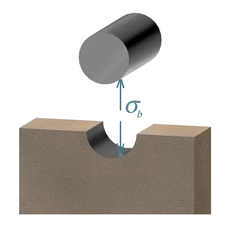
Bearing Stress Definition
Bearing stress refers to the contact pressure that develops at the surface where two separate bodies are pressed against each other, transferring force through their interface. It is not an internal stress within a single component, but rather it acts at the area of contact between components such as bolts, rivets, plates, or foundations and soil. In structural connections, bearing stress typically occurs at the interface between a connector (such as a bolt or rivet) and the plate or material it passes through. This stress is a special case of normal stress, calculated at the region where the force is applied by one member onto another.
Bearing Stress Symbol
Bearing stress is commonly represented by the symbol σb, where the subscript “b” stands for bearing.
Bearing Stress Units
The units for bearing stress are the same as those used for other types of stress:
- Pascals (Pa) in the SI system, most often expressed as Megapascals (MPa), where 1 MPa = 1,000,000 Pa.
- In imperial units, it is typically measured in pounds per square inch (psi).
Bearing Stress Area
The bearing area is the region at the interface of the two bodies where the force is transferred. For bolted or riveted joints, the bearing area is typically the projected rectangular area formed by the diameter of the connector and the thickness of the plate. In formula form:
- Bearing area = connector diameter × plate thickness
- For a washer or footing, the area might be the difference between the outer and inner circular areas if the force is distributed over a ring-shaped area.
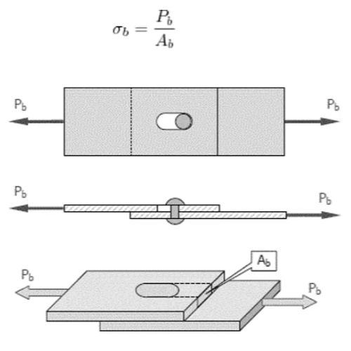
Bearing Stress Diagram
A typical bearing stress diagram for a bolted connection shows a bolt passing through a plate. The force is applied through the bolt, and the rectangular projected area at the bolt-plate interface is the bearing area. Stress is not uniform; it is usually maximum behind the bolt and zero at the sides of the hole, but for calculations, the stress is considered uniformly distributed over the projected area.
[Side View]
 --------------------------
|         Plate           |
|-------------------------|
|   |<--d--> |            |  d = diameter of bolt
|---|  ●     |---         |  t = plate thickness
    |        |
    |        | <--- t --->|
    |        |
Bearing Stress Formula & Equation – How To Calculate Bearing Stress?
The bearing stress is determined by dividing the applied force (typically the load exerted by the connector) by the bearing area:
σb = F / Ab
Where:
- σb = Bearing stress (units: Pascals or N/m²)
- P = force applied (N or lbs)
- Ab = bearing area (mm² or in²)
For a bolted connection:
- Ab = d × t
- d = diameter of the bolt or rivet
- t = thickness of the plate
For circular footings or washers:
- Ab = (π/4) × (Dext² – Dint²)
- Dext = outside diameter
- Dint = inside diameter
Average Bearing Stress Formula
When assuming uniform distribution, the average bearing stress is:
σb,avg = P / (d × t)
Here, the applied force is divided by the projected contact area between the connector (bolt/rivet) and the plate.
Maximum Bearing Stress Formula
In reality, bearing stress is not uniform, it is maximum directly behind the connector and zero at the sides of the hole. However, for most calculations and codes, the maximum bearing stress is often taken as:
σb,max = P / (d × t)
But some advanced analyses might consider the stress concentration, recognizing that actual maximum bearing stress at the edge of the connector can be higher than the average value. Still, design practice usually assumes the average value for simplicity and safety.
Bearing Stress Example
To illustrate how bearing stress is calculated in a real-world scenario, consider a steel plate joined to another plate using a rivet. Suppose the rivet has a diameter of 20 mm, and the plate has a thickness of 7.85 mm. If the force applied through the rivet is 18,849.55 N, we want to find the bearing stress developed at the interface between the rivet and the plate.
Step 1: Determine the Bearing Area
The bearing area is given by the projected contact area between the rivet and the plate:
- Bearing area (Ab) = diameter × thickness
- Ab = 20 mm × 7.85 mm = 157 mm²
Step 2: Apply the Bearing Stress Formula
The bearing stress is calculated as:
- σb = P / Ab
- σb = 18,849.55 N / 157 mm² ≈ 120 MPa
Interpretation
This result means the contact surface between the rivet and the plate experiences a bearing stress of approximately 120 MPa. This value should be compared to the allowable bearing stress for the plate material to ensure that the connection is safe and will not cause the plate to deform or fail locally around the hole.
Visual Summary
[Side View of Plate with Rivet]
   -----------------------
  |         Plate         |
  |-----------------------|
  |   |<--d--> |          |  d = 20 mm (diameter of rivet)
  |---|  ●     |---       |  t = 7.85 mm (plate thickness)
      |        |
      |        | <--- t -->|
      |        |
In this example, the calculation demonstrates the process of determining the bearing stress in a typical riveted connection, using the provided diameters, thickness, and applied force directly from the context of your text.
4. Bearing Stress vs Shear Stress vs Normal Stress: What are the Differences?
As we have introduced each stress type of material with details above, here we sort out the table below to clarify the differences between normal stress, shear stress, and bearing stress for your quick reference:
| Feature | Normal Stress | Shear Stress | Bearing Stress |
|---|---|---|---|
| Direction of Force | Perpendicular to cross-section | Parallel to cross-section | Acts on contact area between bodies |
| Symbol | σ (sigma) | τ (tau) | σb (sigma sub b) |
| Formula | σ = P / A | τ = V / A | σb = P / Ab |
| Units | Pa, MPa, psi, ksi | Pa, MPa, psi, ksi | Pa, MPa, psi, ksi |
| Area Used | Cross-sectional area ⟂ to force | Area parallel to force | Projected contact area (e.g., d × t) |
| Typical Situation | Tension/compression in rods or beams | Pins, bolts, rivets, beams under shear | Plates, bolts, foundations at contact |
| Physical Effect | Stretches or compresses the member | Causes sliding or tearing | Localized stress at interface |
| Failure Mode | Fracture or crushing | Shearing off or sliding | Hole elongation, material yielding |
5. Relationship Between Normal Stress, Shear Stress, and Bearing Stress
These three types of stress are all calculated as force divided by area, yet they arise from different loading conditions and directions of applied force. Normal stress and shear stress are considered the fundamental categories: normal stress results from forces perpendicular to an area, while shear stress comes from forces parallel to an area. Bearing stress, on the other hand, is a specific case of normal stress, where the force is applied at the interface of two separate bodies.
In a structural connection, these stresses often occur together. For example, in a bolted joint, the bolt experiences shear stress as it resists sliding forces, while the plate around the bolt hole is subjected to bearing stress from the bolt pressing against it. At the same time, the plate or member as a whole may be under normal stress due to axial loads.
All three stresses are interconnected through their foundational calculation method (force divided by area), but the distinction lies in the orientation and point of application of the force:
- Normal stress: force normal (perpendicular) to the cross-section.
- Shear stress: force tangential (parallel) to the cross-section.
- Bearing stress: force at the interface, normal to the contact area between different bodies.
Recognizing these differences allows engineers to analyze and design structures and connections that are safe under various types of loading scenarios.