Casting alloy shrinkage is the basic cause of many defects in castings and one of the important casting properties of alloys. What defects will be produced by alloy shrinkage and what factors affect the shrinkage?
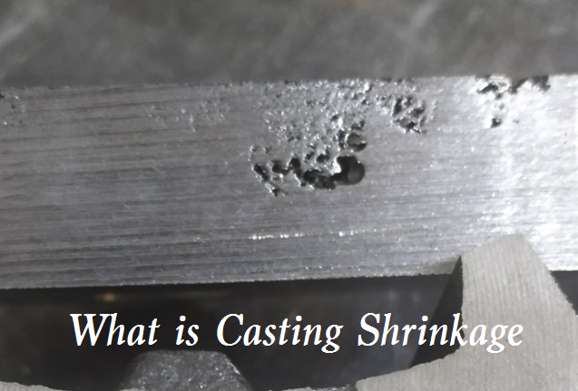
What is Casting Shrinkage
Shrinkage in metal casting is the phenomenon that the volume and size of cast alloys decrease in the process of liquid condensation and cooling to room temperature. As molten metals cool and solidify during the casting process, they tend to reduce in volume. This contraction is a natural result of physical changes in the metal, first as it cools in the liquid state, then as it transforms from liquid to solid, and finally as the solidified metal cools to room temperature.
The shrinkage in casting includes three stages:
- Liquid shrinkage – Liquid shrinkage is the volume reduction of liquid metal due to the decrease in temperature. For example, the liquid shrinkage rate for cast iron is approximately 1.5% to 2.0% (Source: *Foundry Handbook*, 3rd Edition). In this case, the shrinkage primarily affects the gating system design, requiring risers to compensate for shrinkage and prevent shrinkage cavities.
- Solidification shrinkage – Solidification shrinkage is the volume reduction of liquid metal during solidification (liquid state transformation to homomorphism). Liquid shrinkage and solidification shrinkage show the reduction of alloy volume, which is usually called volume shrinkage. Aluminum alloys (such as A356) have a solidification shrinkage rate of 3.5% to 5.2%. This shrinkage is concentrated in thicker parts of the casting, easily leading to shrinkage porosity.
- Solid shrinkage – Solid shrinkage is the volume reduction of metal due to the reduction of temperature in the solid state. Although solid shrinkage also leads to volume reduction, it is usually expressed by the size reduction of metal castings, so it is called linear shrinkage. The linear shrinkage rate for carbon steel is approximately 2.1% to 2.6% (ASTM A48 standard). This shrinkage affects the overall dimensions of the casting and requires compensation through mold enlargement.
The size reduction caused by shrinkage can lead to various casting defects if not properly managed. These defects not only affect the appearance but can also compromise the structural integrity of the finished part.
Casting Defects Caused by Shrinkage
Casting shrinkage not only affects the size but also causes defects such as shrinkage cavity, porosity, internal stress, deformation, and cracking. Therefore, the smaller the shrinkage rate of casting materials, the better. Shrinkage directly affects the quality of castings. If the liquid shrinkage and solidification shrinkage are not supplemented, the casting will have shrinkage cavities and shrinkage porosity defects. If the solid shrinkage is hindered, the casting internal stress will be generated, resulting in the deformation and cracking of the casting.
1. Shrinkage and porosity
Shrinkage cavity is a large concentrated hole that appears at the last solidification of the casting when the liquid shrinkage and solidification shrinkage of the metal are not supplemented. Shrinkage porosity is a small shrinkage cavity dispersed in the casting. Shrinkage cavity and porosity can reduce the mechanical properties of castings, and shrinkage porosity can also make castings leak during air tightness test and hydrostatic test. During production, the shrinkage cavity can be transferred to the riser of the final solidification by setting a riser at the thick wall of the casting, so as to obtain a complete casting. The riser is a redundant part, which can be cut off to obtain a complete and dense casting; It is also possible to prevent shrinkage cavities by reasonably designing the casting structure to avoid local metal accumulation in the casting.
2. Deformation and cracking
During the continuous cooling process of castings after solidification, if the solid shrinkage is hindered, the casting internal stress will be generated. When the internal stress reaches a certain value, the castings will be deformed or even cracked. The internal stress of casting mainly includes mechanical stress and thermal stress during shrinkage. Mechanical stress is the internal stress caused by external forces such as mold and core that hinder shrinkage; Thermal stress is the internal stress caused by the uneven shrinkage of different parts of the casting during cooling and solidification.
In production, in order to reduce the internal stress of casting, we often start with improving the casting structure and optimizing the casting process, such as the wall thickness of the casting should be uniform, or reasonably setting chill and other technological measures to make all parts of the casting cool evenly and solidify at the same time, so as to reduce the thermal stress; The structure of the casting shall be simple and symmetrical as far as possible, so as to reduce the shrinkage obstruction of the metal and reduce the mechanical stress.
What Factors Affect Shrinkage?
The factors affecting shrinkage are divided into internal and external conditions.
1) Type and composition of alloy
The shrinkage rate varies with the type and composition of the alloy. The shrinkage rate of gray cast iron in iron carbon alloy is small, and that of cast steel is large. The following figure shows the linear shrinkage of commonly used cast alloys.
2) Process conditions
The pouring temperature of metal has an effect on the shrinkage. The higher the pouring temperature is, the greater the liquid shrinkage is. Casting structure and mold material also have an impact on shrinkage. The more complex the cavity shape is, the worse the concession of mold material is, and the greater the obstruction to shrinkage is. When the structural design of the casting is unreasonable and the yielding of the mold material is poor, the casting will produce casting stress due to blocked shrinkage, which is easy to produce cracks.
Types of Shrinkage in Casting
Shrinkage defects appear because metal alloys contract during cooling. It is normal for an alloy piece to shrink as it solidifies. However, problems arise when this shrinkage is uneven, distorting the final product or creating interior voids. Shrinkage can be grouped mainly into the following categories:
-
Cavity Shrinkage (Open Shrinkage Defects)
Cavity shrinkage happens when two separate sources of molten metal come together during the casting process. This joining can leave voids or cavities within the casting, especially if the molten materials do not fuse perfectly. These defects usually form in regions where the metal solidifies last, leaving pockets behind.
Cause:
This type of shrinkage is often due to improper feeding of molten metal or poor gating system design that fails to maintain a continuous supply of metal as the casting cools.Prevention:
To avoid cavity shrinkage, it’s important to use well-designed risers and gating systems that ensure a consistent flow of molten metal into all sections of the mold until solidification is complete. -
Sponge Shrinkage (Closed Shrinkage)
Sponge shrinkage typically appears in the thicker central parts of a casting, where the metal cools more slowly. In these areas, dendrites, branch-like metal crystals, develop, creating a spongy internal structure full of tiny voids.
Cause:
This occurs when the thicker mid-sections of the casting product solidify later than the outer regions, causing a network of small cavities as the metal contracts and dendrites form.Prevention:
To minimize sponge shrinkage, proper temperature control and the use of chills or external cooling methods help achieve more uniform cooling throughout the casting. This ensures the interior and exterior of the part solidify more evenly. -
Filamentary Shrinkage
Filamentary shrinkage is marked by the presence of continuous cracks or fissures in the casting, which can vary greatly in size and density. These filament-like cracks often run through the casting and compromise its overall strength.
Cause:
This type of shrinkage is usually the result of uneven cooling or inadequate feeding of molten metal, which creates tension and cracking as the metal contracts.Prevention:
To avoid filamentary shrinkage, the mold should be designed to encourage uniform solidification. Using risers and proper gating, along with ensuring the molten metal remains fluid long enough to fill all areas, can greatly reduce the risk of these cracks. -
Dendritic Shrinkage
Dendritic shrinkage is identified by narrow fractures or cavities that are randomly distributed, often following the pattern of dendritic crystal growth. These lines or voids appear inside the casting and are associated with the formation of dendrites during the solidification process.
Cause:
Dendritic shrinkage occurs as the metal cools and the dendritic structures form, leaving behind narrow, dispersed lines or cavities in the casting.Prevention:
Prevention involves optimizing the cooling rate and ensuring good feeding during solidification. Carefully controlled temperature gradients and the use of chills can help direct solidification and minimize the growth of dendritic fractures.
Casting Shrinkage Allowance Chart
Have you ever wondered how manufacturers ensure that metal parts fit perfectly after they are cast? One key factor in this process is something called shrinkage allowance. Shrinkage allowance refers to the intentional increase in the dimensions of a pattern or mold. This adjustment compensates for the contraction that occurs when molten metal cools and solidifies. So what exactly is the shrinkage allowance in casting? Here we’ve sorted out the Casting Shrinkage Allowance Chart for the main metal materials, including steel, cast iron, brass, aluminum, zinc, and magnesium:
| Material | Shrinkage Allowance (%) | Shrinkage Allowance (mm/m) | Typical Notes / Range |
|---|---|---|---|
| Grey Cast Iron | 0.7 – 1.2 | 7 – 12 | Lower due to graphite expansion |
| White Cast Iron | 2.1 | 21 | |
| Malleable Iron | 1.5 | 15 | |
| Ductile Iron | 0.9 – 1.4 | 9 – 14 | Lower due to spheroidal graphite |
| Steel (Carbon/Alloy) | 2.0 – 2.6 | 20 – 26 | Higher, lacks graphitization |
| Stainless Steel | 1.5 – 2.0 | 15 – 20 | |
| Brass | 1.4 | 14 | |
| Bronze | 1.05 – 2.1 | 10.5 – 21 | |
| Aluminium | 1.8 | 18 | |
| Aluminium Alloys | 1.3 – 1.8 | 13 – 18 | Die cast: 0.5–0.7%; wrought: 1.0–1.8% |
| Magnesium | 1.8 | 18 | |
| Zinc | 2.5 | 24 | |
| Manganese Steel | 2.6 | 26.5 | |
| Copper Alloys | 1.2 – 1.8 | 12 – 18 | Brass & bronze in this range |
This cast shrinkage chart provides a practical reference for patternmakers and foundry engineers to quickly apply the correct casting shrinkage allowance for common metals in their projects.
Casting Shrinkage Formula & Calculation
Calculating the correct mold dimensions requires applying a straightforward shrinkage formula. The basic approach involves multiplying the finished dimension by the shrinkage rate, then adding this value to the original size to determine the pattern or mold size.
Formula:
Mold Size = Finished Part Size × (1 + Shrinkage Rate)

![]()
Or, for small shrinkage values and practical work:
Shrinkage Allowance = Finished Dimension × Shrinkage Rate
Mold Size = Finished Dimension + Shrinkage Allowance
![]()
Example Calculation:
Suppose you wish to cast a steel rod with a final length of 100 mm. With a steel shrinkage rate of 2%, the calculation would be:
- Shrinkage allowance = 100 mm × 0.02 = 2 mm
- Mold length = 100 mm + 2 mm = 102 mm
For a more detailed case, consider aluminum alloys. If a casting requires a final length of 200 mm and the shrinkage rate is 1.5%, the necessary pattern length would be:
- Shrinkage allowance = 200 mm × 0.015 = 3 mm
- Mold length = 203 mm
In engineering practice, you may encounter formulas with a compensation coefficient (such as 1.008–1.012 for gray cast iron, 1.013–1.018 for aluminum alloys, and 1.021–1.026 for carbon steel, as shown in the images). These can be used directly:
- For a 150 mm aluminum part (shrinkage coefficient 1.015):
Mold length = 150 mm × 1.015 = 152.25 mm
When working with complex shapes or alloys with varying shrinkage behaviors, it’s wise to check actual finished part measurements and adjust your calculations for future runs.
How To Design For Shrinkage In Casting?
Designing for shrinkage in casting begins with understanding that all metals contract as they cool and shift from liquid to solid. The amount of shrinkage is influenced by the alloy, mold type, casting method, and geometric complexity. The first step is to select the correct shrinkage rate using reference charts or past experience, then apply the calculated allowance directly to your mold or pattern design.
Step-by-Step Process:
-
Identify Material and Process:
Choose the alloy and casting method. Each combination brings its own shrinkage characteristics. For example, aluminum sand casting generally has a shrinkage rate of 1% to 1.5%, while steel can range from 1.5% to 2% or higher. -
Determine Shrinkage Allowance:
Use published tables or historical measurements to find the right rate. Apply the shrinkage formula to each dimension, adding the allowance to get the mold size. -
Adjust Mold Geometry:
For castings with varying wall thicknesses, remember that shrinkage may not be uniform. Thick sections tend to shrink more and may develop internal voids if not properly fed with molten metal. Incorporate risers or feeders to supply additional metal as the part cools, reducing the risk of cavities. -
Consider Solidification Direction:
Design the gating and riser system so that thinner parts solidify before thicker ones. This encourages directional solidification, which helps control where shrinkage occurs and reduces the risk of defects. -
Apply Cooling and Venting Features:
For parts prone to uneven cooling, add cooling ribs, chills, or vents to promote uniform solidification. This limits the formation of shrinkage cavities and warping. -
Account for Machining Allowance:
Reserve extra material where precision finishing is required, especially for metals with higher shrinkage rates, such as steel. The machining allowance is determined based on both the shrinkage rate and expected dimensional variations. -
Validate and Refine:
Once the initial casting is produced, measure the final dimensions and compare them to the pattern. Adjust your shrinkage allowance as needed for future production runs. Keep detailed records of shrinkage rates for each material and process.
Practical Tips:
When working with simple shapes, start by applying the standard allowance and measure the results. For complex castings or new materials, consider using casting simulation software to predict shrinkage and optimize the gating and feeding system. Always keep in mind that differences in raw material batches, equipment conditions, and operator technique can affect actual shrinkage, so ongoing monitoring and adjustment are vital.