
What is a Sprue in Die Casting – Difference Between Sprue and Runner | Diecasting-mould
The design of die casting mold allows manufacturers to get a complete product that does not need assembly, however, it may leave some excess material that needs to be removed from the casting. Sprue is one of the causes. What is a sprue in die casting? What is the difference between sprue, runner and gate?
What is a Sprue in Casting?
A sprue is a vertical passage through which the molten material flows into the casting mold, it is the first channel for liquid metal to enter the mold cavity, and it is also the primary part of pressure transmission, so its size will affect the flow speed and filling time of liquid metal. The sprue connects the pouring basic to the runner, it is usually tapered downwards to minimize turbulence and the formation of air bubbles. The sprue is used to guide the metal down from the sprue gate into the runner, inner gate, or directly into the cavity. It provides enough pressure to make the liquid metal overcome all kinds of flow resistance under the action of gravity, and fill the cavity within the specified time. Common shapes of sprue including the cone shape with a big top and small bottom, the column shape with equal section, and the inverted cone shape with a small top and big bottom. For magnesium and aluminum alloy castings, serpentine, flaky and slit sprues are also used. In the die casting process, the material in the sprue will solidify and need to be removed from the finished part.`
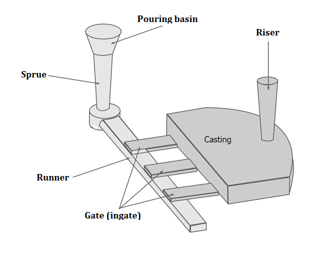
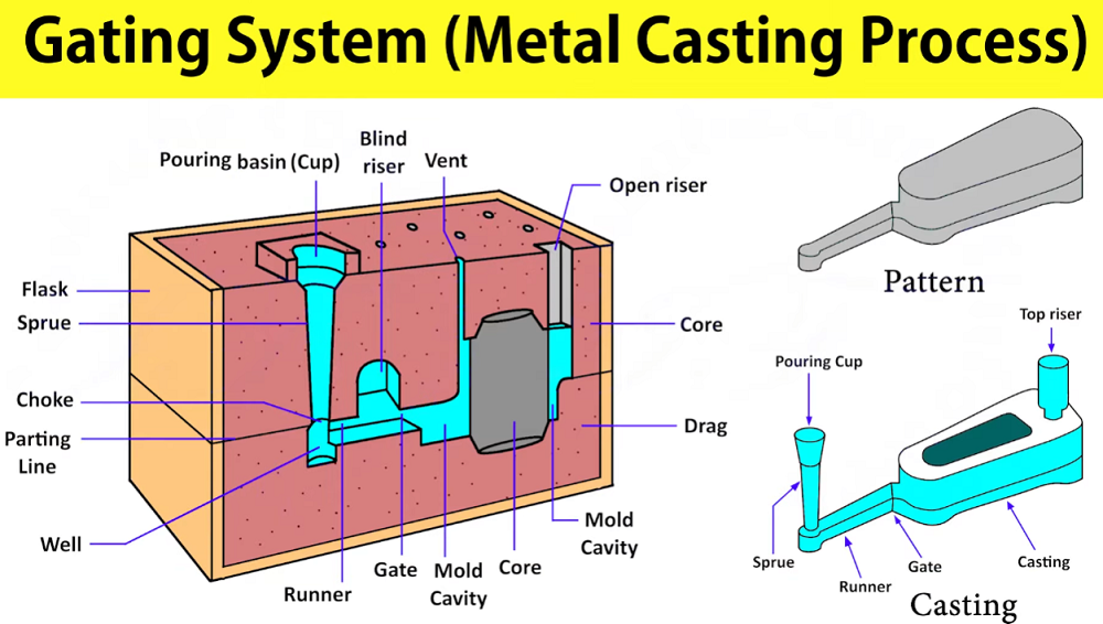
Here is the simple structure of the gating system, you can find the sprue, runner, and gate in it. (image is from google)
Function of Sprue in Casting
Sprues are a vital part of the casting process, and their importance cannot be overstated. When preparing files for casting, the type, size, and placement of sprues depend on several factors, including the type of metal, as well as the thickness, height, and depth of the piece.
- Simplifying Casting for Basic Designs
Generic items like rings and pendants are a lot easier to make. For these types of pieces, casting is rarely complicated. A shank that is relatively easy to fill, for example, has a half solid piece that comes into a setting on the top. It is simply cast by putting a sprue on the bottom, which is a straightforward and effective approach.
- Addressing Complexity in Intricate Pieces
More intricate objects, including under galleries, settings, tops of rings, organic material, and very heavy pieces, require a variety of sprues during casting. In cases where a simple sprue cannot be placed on the bottom, top, or sides, creative solutions are necessary. For example, an eternity band cannot have a sprue simply stuck on the bottom or the top or the sides or anything. In such situations, a spruing system is created to give metal equally around the ring, resembling the spokes of a bicycle wheel. Sometimes multiple sprues are required, depending on the complexity of the design.
- Ensuring Complete Metal Flow and Avoiding Defects
Certain pieces have many dips and turns and may also carry stones on the top side with little prongs. In these cases, sprueing on the bottom is sometimes the only way to ensure the piece comes out successfully. However, this method has its complications, especially when dealing with the thickness of the piece itself. The solution may involve creating a cage-like structure to support the mold during casting.
- Strategic Sprue Placement for Integrity and Quality
Sprue placement is critical in ensuring the integrity of the cast piece. For example, connecting the sprue at points where elements of the design meet, such as where the D meets the A, where the loop of the A meets the D, or where the ending of the D is just hanging in space, prevents parts from breaking off during casting. Arranging the piece to be cast upside down can help fill all the separate sections in one shot, preventing shrinkage and porosity.
- Facilitating Finishing and Cleanup
A well-planned sprue system is also helpful for those responsible for cleaning the piece after casting. It allows the sprue to be cut off in one shot, making it easier to finish the piece and ensuring efficiency in the manufacturing process.
Practical Examples:
- Simple Shank:
A straightforward ring shank can be cast with a single sprue on the bottom.
- Intricate Letter Piece:
For designs with multiple intersections (like a piece shaped with letters), sprues are strategically placed where different elements meet. This ensures all sections are filled, prevents breakage during casting, and makes post-casting cleanup easier.
Difference Between Sprue and Runner
The flow path into the mold cavity consists of a sprue, runner, and gate. How do they work, and how to distinguish them?
1. The sprue is the first channel for liquid metal to enter the casting mold, then the metal flows into the runner.
2. A sprue is a large-diameter channel through which the material enters the mould. A runner is a smaller diameter channel that directs the molten metal towards the individual part. A similar example can be found in a water system that uses a water main (gate) and a smaller pipe (runner) to each house.
3. A trapezoid runner or round runner design is desirable, there is a wide variety of shapes of the sprue.
Difference Between Sprue and Gate
Sprue and gate are different parts of the gating system and have different functions. So the die casting sprue and gate differ in shape, size, position and more aspects.
1. The sprue is the channel of the material that leads into the runner, and then flows into the mold cavity through the gate. The sprue may be considered the continuation of the mold to the nozzle of the casting machine. The sprue needs to be large enough to fully pack the cavity. The cone-shaped sprue with a big top and a small bottom is in the full flow state, while the sprue with equal cross-section and inverted cone-shaped sprue with small top and the big bottom is in the nonfull flow state.
2. The gate is at the end of the runner, leading into the mold cavity. It is small and designed to freeze before the part, runner, or sprue freeze. Usually, the gate is smaller than the wall thickness of the part. But too small gate can cause defects, tool wear, and incomplete filling. Gate size is determined by filling speed and component thickness.