The Optimized Process Plan For Development Of Die Cast Aluminum Alloy Beams | Diecasting-Mould
This article uses as an illustration the manufacturing process of die casting aluminum alloy beams and makes the creation process transparent using MAGMASOFT. The structure’s best castability is realized by casting parameter calculation and structural analysis. Then several pouring programs can be simultaneously input into the software and pick the most optimized pouring method. The best die casting method parameters are derived from DoE big data comparative study. This article restores the die casting program creation phase of the product and systematically shows development ideas to provide an idea for applicable engineering and technical workers in the industry.
The Optimized Process Plan For Development Of Die Cast Aluminum Alloy Beams
1. Basic introduction of castings
The basic casting size is 416mm.182mm.22mm; weight is 4.45kg and material grade is ADC12. This product’s overall wall thickness is relatively uniform, with 4.3mm average wall thickness. The beams must be assembled and welded, making porosity and profile requirements very high. Based on the product’s characteristics and consistency specifications, an appropriate gating device must be built to ensure sequential filling of molten metal and reduce flow porosity and gas porosity. At the same time, there is a very wide window area in the center of the package, which caused a major obstacle to molten metal filling. Therefore at the end, we must pay great attention to the product’s molding condition.
2. Preliminary calculation and analysis
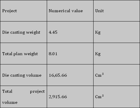
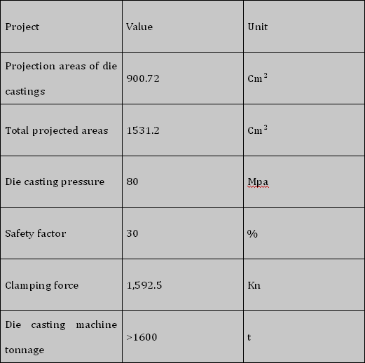
In the early stage of product creation, insert blank 3D into MAGMASOFT and the program can automatically measure the basic data including the volume, weight, cross-sectional area and estimated area of product. Then MAGMASOFT calculates the die casting machine tonnage needed to manufacture the product and matches the corresponding machine from the software machine database, as shown in the forms.
Calculation of basic product attribute information
Calculation of die casting machine tonnage
After deciding the die casting unit, the user inputs the product’s average wall thickness according to the product’s structural characteristics, and MAGMASOFT calculates all process parameters including filling rate, low speed and high speed switching location, high speed, internal gate cross-sectional area, filling time and internal gate speed. The software also recommends best related data such as molding time, molding time and low speed, high speed switching location, high speed and cross-sectional internal gate area. The user can input various parameters based on the factory machine’s actual output, and then the program will produce a database parameter such as the inner gate’s cross-sectional area and inner gate speed.
3. Analysis of gating and discharge systems
3.1 Selection of the gating system
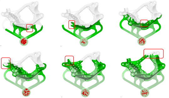
All the pouring possibilities are input to the software according to the internal gate cross-sectional area determined by the software and the product structure. For the analysis of gating, we have 4 plans, they are as follows: Plan 1 has a total of five gates, which are equally distributed. And the pouring is balanced, which can realize the overall pouring. The pressure is relatively uniformly transmitted to ensure density. Attention should be given to the filling area at the top. There is a chance of cold material accumulation and filling and bad exhaust. Plan 2 has a total of three gates, and the high-volume region of the commodity corresponds to the large gate to ensure the filling efficiency and pressure transmission. However, thick gates can easily cause partial temperature to be too high causing deformation and bad effects on the mold. Meanwhile this positioning will lengthen the filling stroke. Plan 3 and Plan 4 each have a total of three gates, and the high-volume region of the commodity corresponds to the large gate to ensure the filling efficiency and pressure transmission. However, thick gates are likely to induce excessive partial temperature, causing deformation and adverse effects on the mold.
The program completes the estimation of the four plans by setting up process conditions and performs multi-dimensional big data statistics. The program recommends Plan 1 as the best pouring plan to test the smooth aluminum liquid flow.
3.2 Determination of discharge system
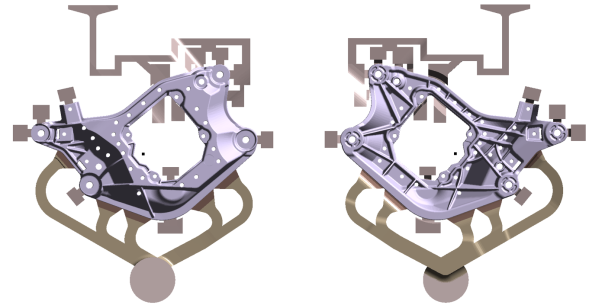
After verifying the pouring plan and following the suggested plan 1, the product flow analysis is performed. The below figure shows the confluence of flow pattern and the location of the end of flow according to flow pattern direction. At the confluence and end of molten aluminum flow, a discharge system is added to efficiently discharge the cold material and ensure casting consistency.
4. Optimization of DoE process parameters
After deciding the gating mechanism, the process parameters of die casting must be planned and determined. MAGMASOFT’s independent optimization tool helps engineers to explore the wider design space by recognizing the effect of process variables on casting efficiency, and finding optimal die casting mold and process layout plan.
Using the DoE autonomous optimization tool, the die casting process parameters are optimized based on completing gating device configuration. High speed is a key parameter affecting aluminum filling and product consistency. Take the DoE optimization process as the research object for study. Set high-speed speeds from 3.5 to 4.0m/s and set the iteration phase size to 0.1 to minimize gate speed and cold shutdown defect. After software review of big data and statistics, the best molding process parameters are recommended. Choosing a high-speed 3.5m/s not only suits the low gate speed, eliminates mold filling corrosion, but also ensures product consistency.
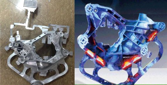
5. Product research results
Through the MAGMASOFT standard pouring planes and parameter designs, the gating and discharge device designs and die casting process parameters were completed and the data was used as a reference for actual verification. A 1600T die casting machine was selected and aided by a vacuum system for the first test production, and the test production was conducted according to DoE optimized die casting parameters. The figure below is the first trial casting diagram. Internal casting quality is found to be reasonably ideal by detecting internal quality X-ray. Internal consistency defects, such as gas porosity, shrinkage porosity, and shrinkage, all comply with ASTM F 5051. There are no welding defects in the welding area after welding, which proves the product’s internal gas content is very low. The first production trial was successful. The first trial production enters the mass production state, which significantly saves costs and decreases the development period.