Surface Defects Of Aluminum Alloy Die Castings With Causes & Solutions | Diecasting-Mould
As one of the lightweight materials for automobiles in the market, the aluminum alloy material is widely used for auto parts die casting enterprises. Various factors affect quality of aluminum alloy die castings in the actual production process. In this article, we explain the surface defects of aluminum alloy die castings, what causes aluminum alloy die casting surface defects and what’s the solutions. Hope this will help people who work in the die casting industry.
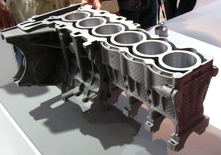
Surface Defects Of Aluminum Alloy Die Castings – Causes & Solutions To Aluminum Die Casting Defects
Here we list all the surface aluminum die casting defects, with each features, causes and solutions.
1. Cuts
(1) Features
① Linear cuts appear with a certain depth on the surface of the die casting along the mold opening direction, and cuts occur on the whole surface in a serious situation.
② The molten metal sticks to the mold surface, resulting in a lack of materials on the surface of the die casting.
(2) Causes
① The surface of the mold cavity is damaged.
② The mould striping direction has no inclination or the inclination is too small.
③ The ejection is unbalanced.
④ The mold is loose.
⑤ The die casting temperature is too high or too low, and the mold temperature is too high to cause the sticking of alloy liquid.
⑥ The effect of mold release agents is not good.
⑦ The iron content of aluminum alloy composition is less than 0.8% and the cooling time of the mesh is too long or too short.
(3) Solutions
① Repair damage on the mold surface.
② Modify the inclination to improve smooth finishes on the surface of the mold.
③ Adjust the ejector rod to balance the ejection force.
④ Fasten the mold.
⑤ Control the reasonable die casting temperature and mold temperature, from 180 to 250℃.
⑥ Replace the release agent.
⑦ Adjust the iron content of aluminum alloy.
⑧ Adjust the cooling time.
⑨ Modify the inner gate and change the direction of the molten aluminum.
2. Bubbles
(1) Features
A rice grain like cavity is formed under the skin of the die casting.
(2) Causes
① The filling of the alloy liquid in the pressure chamber is too low; gas is easy to be cased in the molten metal, the injection speed is too high.
② The mold exhaust is poor.
③ The melt is not degassed, and the melting temperature is too high.
④The mold temperature is too high; the metal solidification time is not enough; the strength is not enough, the die casting is ejected prematurely, and the pressurized gas expands.
⑤ There are too many release agents.
⑥ The inner gate is not set properly, and the filling direction is crossed.
(3) Solutions
① Make the diameter of the die casting chamber smaller to increase the fullness of molten metal.
② Extend the injection time; reduce the injection speed in the first stage, and change the switching point between low speed and high speed injection.
③ Reduce the mold temperature to maintain thermal balance.
④ Add exhaust grooves and overflow grooves to fully exhaust and remove oil and waste on the exhaust grooves in time.
⑤ Adjust the smelting process and perform degassing treatment.
⑥Properly extend the mold retention time.
⑦ Reduce the amount of release agent.
3. Cracks
(1) Features
① The surface of the die casting has linear or wavy lines, which are narrow and long and can be increased under the action of external force.
②The metal in the cold crack part is not oxidized.
③ The metal at the hot crack part is oxidized.
(2) Causes
① The iron content or the silicon content in the alloy is too high.
② The content of harmful impurities is too high, which reduces the plasticity of the alloy.
③ Al-Si-Cu alloy contains too high zinc content or too low copper content.
④ The mold, especially the overall temperature of the cavity is too low.
⑤ Shrinkage is stopped where there are drastic changes in the wall thickness and thinness of the die casting, and stress is formed at the sharp corners.
⑥ The mold retention time is too long and the stress is great.
⑦ The force is uneven during ejection.
(3) Solutions
① Correctly control the alloy composition. In some cases, pure aluminum ingots can be added to the alloy to reduce the magnesium content in the alloy, or aluminum silicon intermediate alloys are added to the aluminum alloy to increase the silicon content.
② Change the die casting structure; add angles; change the inclination of the mold, and reduce the difference in wall thickness.
③ Change or add the ejection position to make the ejection force uniform.
④ Shorten the time of mold opening and core pulling; increase mold temperature and maintain mold thermal balance.
4. Deformation
(1) Features
① Overall or partial deformation appears.
②The geometry of the die casting does not match the drawings.
(2) Causes
① Poor casting structure
② The mold is opened too early, and the rigidity of the die casting is not enough.
③ The ejector rod is improperly set, and the force is uneven when the die casting is ejected.
④ The thickness of the inner gate position or sprue is too thick, and it is easy to deform when the gate is cut.
⑤ The partial surface roughness of the mold causes great resistance, and the product deforms when ejected. The partial temperature of the mold is too high; the product is not completely solidified; the ejection force is great, causing product deformation.
(3) Solutions
① Improve the casting structure.
② Reasonably adjust the holding pressure and mold opening.
③ Reasonably set the ejector position and the amount of ejector pins, preferably 4 in an open place.
④ Change the gate position to make the gate have a point; reduce the thickness of the gate. Ensure die casting quality of the product and make it as as criterion so that the product will not be easily deformed when the gate is removed.
⑤ Strengthen the mold surface treatment to reduce the demolding resistance.
⑥ Control the partial mold temperature loss to maintain the mold thermal balance.
5. Flow marks or patterns
(1) Features
There are stripes that are consistent with the flow direction of the molten metal on the surface of the die casting, and they are obvious non directional lines which are different from the metal matrix in color. There is no development trend.
(2) Causes
① The molten metal that first enters the cavity forms a very thin and incomplete metal layer, which is compensated by the subsequent molten metal, forming a mark.
② The mold temperature is too low and the mold temperature is uneven.
③ The cross-sectional area of the inner gate is too small and the location is improper, resulting in splashing.
④ The pressure acting on the molten metal is insufficient.
⑤ Excessive amount of paint cause marks.
(3) Solutions
① Increase the temperature of the molten metal by 620% to 650℃.
② Increase the mold temperature and maintain a heat balance of 200℃ to 250℃.
③ Thicken the cross-sectional area of the inner runner and change the inlet position.
④ Adjust the filling speed and injection time stroke length.
⑤ Select appropriate paint and adjust the concentration.
6. Cold shuts
(1) Features
Obvious, irregular and sinking linear lines both penetrating and non penetrating appear on the surface of the die casting, which are small and narrow. Some of the junction edges are smooth, which can be developed under the action of external force.
(2) Causes
① The two metal flows are connected to each other, but they are not completely fused and there are no inclusions in between. The bonding force of the two metals is very weak.
② The pouring temperature or die casting temperature is too low.
③ Alloys are selected improperly and have poor fluidity.
④ The runner position is wrong or the flow path is too long.
⑤ The filling speed is low and the injection specific pressure is low.
(3) Solutions
① Increase the pouring temperature and mold temperature appropriately.
② Increase the injection specific pressure and shorten the filling time.
③ Increase the injection speed while increasing the cross-sectional area of the inner gate.
④ Improve exhaust and filling conditions.
⑤ Select alloys correctly to improve their fluidity.
7. Different colors and spots
(1) Features
Different colors and spots appear on the surface of the casting.
(2) Causes
① Composition of the release agent falls into the surface of the die casting
② The filling is too much, and it accumulates partially.
③ The regular solidification of graphite causes the molten metal temperature to be too low.
(3) Solutions
① Replace a release agent with high quality.
② Strictly control the spraying amount and spraying operation.
③ Control mold temperature and maintain thermal balance.
④ Control the temperature of molten metal.
8. Mesh burr
(1) Features
Mesh like shape appears on the surface of the die casting part.
(2) Causes
① The surface of die casting cavity is cracked.
② Materials of die casting molds are improper or the heat treatment process is incorrect.
③ The temperature difference between the hot and cold of the die casting mold varies greatly. Because the die casting temperature is too high, the die casting mold is insufficiently preheated, and the surface of the round cavity is rough.
(3) Solutions
① Correctly select die casting molds and hot spots, especially high field alloys.
② After the mold is manufactured, aging treatment or chemical oxidation treatment on the surface should be carried out.
③ Polish the surface of the molded part to reduce the surface roughness, and the Ra value should be from 0.8 to 0.4.
④ Choose the mold cooling method reasonably.
⑤ Avoid intensive cooling of the mold surface.
9. Dents
(1) Features
There are dents on the smooth surface of the die casting.
(2) Causes
① The wall thickness of the die casting is too different, and most of the dents are generated in the thick wall.
② The mold is partially overheated, and the overheated part solidifies slowly.
③ The injection specific pressure is low.
④ The cavity gas cannot be discharged due to the high temperature of the mold, and it is compressed between the surface of the cavity and the surface of the molten metal.
(3) Solutions
① The design of wall thickness of the die casting should be as uniform as possible.
② Partial cooling of the mold should be adjust.
③ Increase injection pressure.
④ Improve exhaust conditions of the cavity.
10. Shortages of the die cast1
(1) Features
There is insufficient pouring on the surface of the die casting and the outline is not clear.
(2) Causes
① The reason is the poor fluidity.
② The alloy liquid absorbs gas and oxide inclusions, and the iron content is high, which make its quality poor and reduce the fluidity.
③ The pouring temperature is low or the mold temperature is low.
④ The filling condition is poor.
⑤ The specific pressure is too low.
⑥ Too much gas is cased in the molten metal. The back pressure of the cavity becomes higher, and the filling is blocked.
⑦ Improper operation, excessive painting and paint accumulation make the gas cannot be volatilized.
(3) Solutions
① Improve quality of alloy liquid.
② Increase pouring temperature or mold temperature.
③ Increase specific pressure and filling speed.
④ Improve the guide method of molten metal in the pouring system, and add overflow grooves and exhaust grooves at the parts which are short of molten metal.
⑤ Check whether the capacity of the die casting machine is good or not.
11. Burr
(1) Feature
Metal thin sheets appear on the edge of the parting surface of the die casting.
(2) Causes
① The mold clamping is not enough.
② The injection speed is too high, resulting in too high pressure shock peak.
③ The debris on the parting surface is not cleaned.
④ The mold strength is not good enough to cause deformation.
⑤ Inserts and sliders are worn and not aligned.
(3)Solutions
① Check the clamping force and pressurization, and adjust the die casting process parameters.
② Clean the cavity and parting surface.
③ Repair the mold.
④ It is best to use a closed injection end time control system, which can obtain die castings without burr.