Creating unfold drawings for sheet metal fabrication can be a complex task, especially when dealing with intricate shapes and designs. While many engineers rely on software like SolidWorks (SW) for this work, using Computer-Aided Design (CAD) tools can be an efficient alternative, particularly under heavy workloads. Let’s delve into how to use CAD for making sheet metal unfolding drawings, starting with the basic unfolding calculations.
Sheet Metal Unfolding Calculation Guide – How To Unfold Sheet Metal Step By Step
1. Unfold at right angles
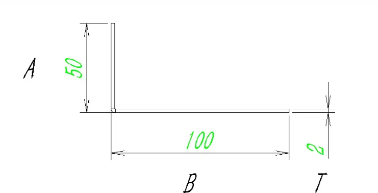
This situation is the simplest, usually we calculate by deducting 1.7 per millimeter of plate thickness, that is: L=A+B-1.7T. (Note: 1.7 is the value for cold-rolled sheet and galvanized sheet. If it is stainless steel sheet, copper sheet, or aluminum sheet, it needs to be taken separately. You can test how much should be taken on the bending machine.)
2. Expand from a large angle
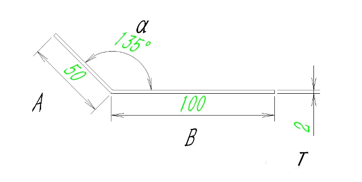
This situation is also quite common, and the formula is: L=A+B – (180- α) T. Note: This angle cannot be used as a reference and usually requires welding support on the side to ensure the angle. (Note: A and B are both measured to the virtual intersection, the same below.)
3. Small angle unfolding
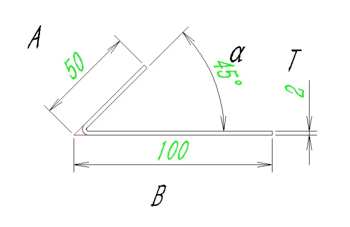
This situation usually does not require too high accuracy, and the formula is L=A+B – {tan (180- α)/ 2} T.
Next, let’s take a simple box as an example to see how the actual unfolds:
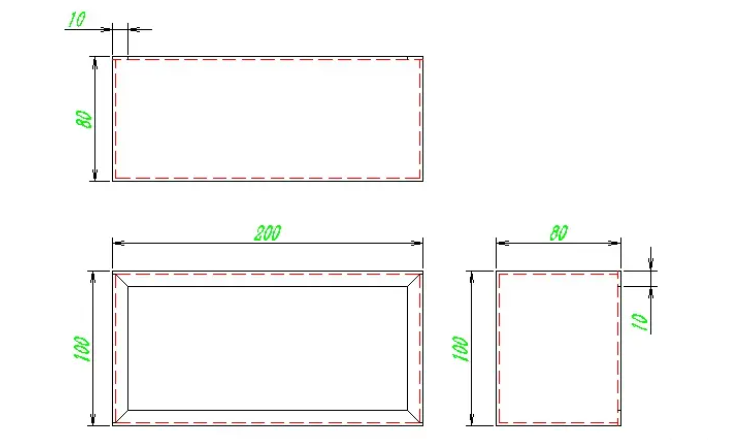
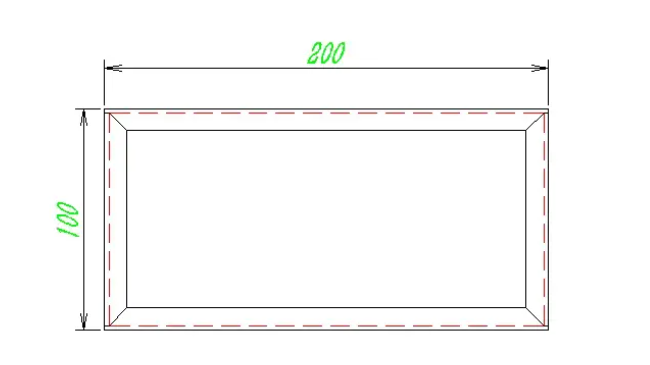
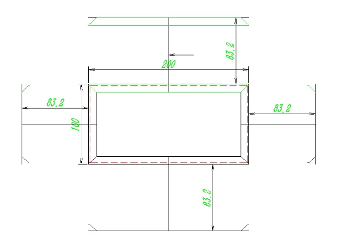
As shown in the figure, this box has a length of 200, a width of 100, a height of 80, and a folded edge of 10. Therefore, bending requires 8 cuts, which is 4 cuts each from 10 to 80. Let’s first make a copy of the main view:
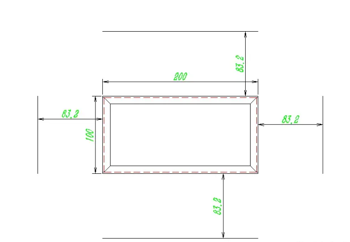
The folded edge is 80-10, and calculated based on the cold-rolled plate thickness of 2.0, the deduction for each blade is 3.4,90-3.4 * 2=83.2. We offset 83.2 from each edge line, as shown in the following figure:
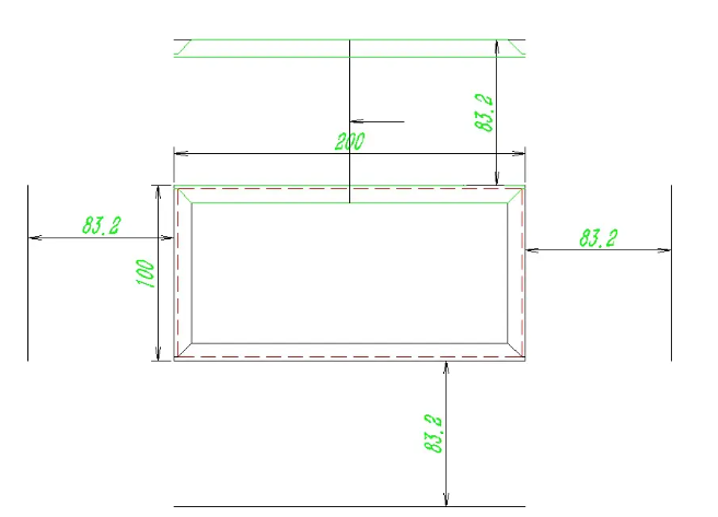
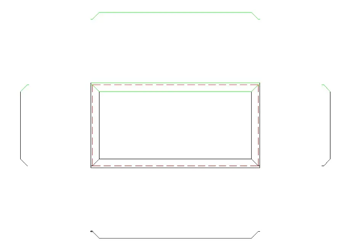
First, draw a line from the midpoint of the folded edge at the end to the midpoint of the offset line, and then mirror the green part onto the center point of this line, as shown in the figure:
Note: The prerequisite for this step is that there is no problem with forming the three views, otherwise it will definitely be incorrect later. Then the other three directions are also mirrored in this way. As shown in the following figure:
Next, delete all the previously offset lines, and remove any excess annotations, lines, and so on. As shown in the following figure:
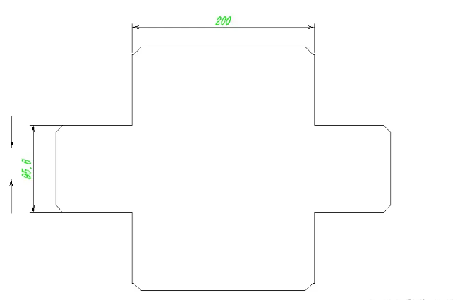
Then connect the parts that are offset around, as shown in the following figure:
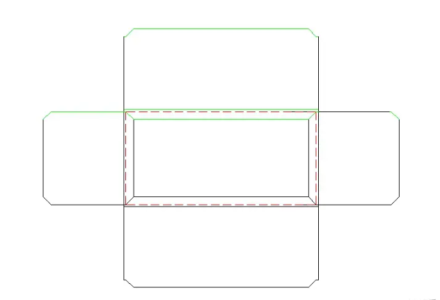
Then remove all excess lines inside. As shown in the following figure:
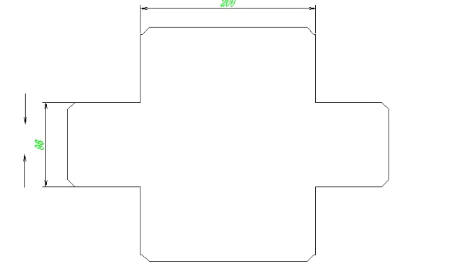
Attention: At this point, the width of the horizontal edge is 96, while the total width of the box formed is 100, so there is no gap. When bending, it is easy to deform due to compression. Therefore, it is necessary to shrink the edge of 96 a bit, and each side should be reduced by 0.2.
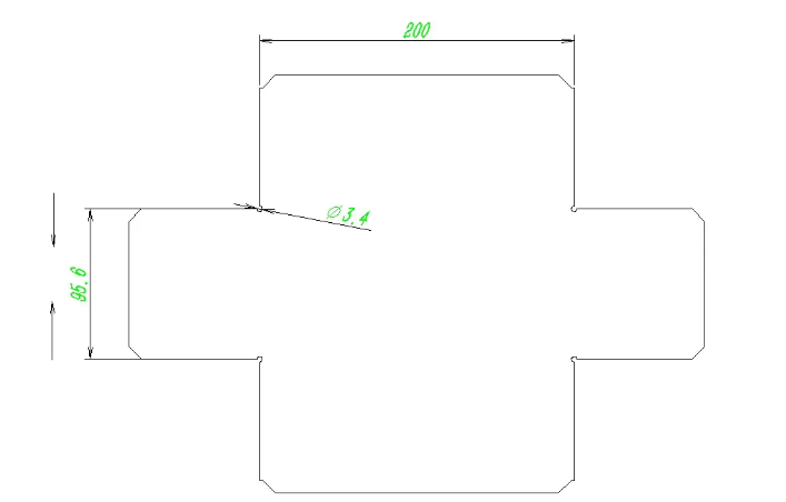
Last step: Process hole, usually used for sheet metal with a thickness of 1.5 and above. At the folding edge of the corner, if no process hole is opened, it will be squeezed and deformed. We usually open a hole at the intersection of the connecting lines that is equal to the bending minus the diameter, as shown in the following figure:
Remember, while CAD can automate many aspects of the unfolding process, a good understanding of sheet metal fabrication principles is still essential for creating accurate and functional designs. Practice and experience, combined with the capabilities of CAD software, will enhance the precision and efficiency of your sheet metal unfolding projects.