
Core and cavity are usually found in the sand casting process, including cast iron, cast copper, cast aluminum, and cast steel. The core and cavity are the main working parts of the casting mold and the key components used to shape the parts. What is the difference between mold core and cavity? And what requirements need to reach when making mold core and cavity?
What is Mold Core?
Mold core, also called sand core, is the filler for making the inner cavity shape of castings, including three types of inner sand core, outer core, and sand filling core; The inner sand core is used to make the inner cavity of the casting, and the role of the outer core box is to supplement the sand core. The sand core is required for the parts that cannot be directly drawn and formed.
What is Mold Cavity?
The mold cavity is the gap formed by the combination of sand mold and sand core after the completion of the sand mold, including the mold cavity of the casting and the mold cavity of the gating system. These mold cavities are filled with molten metal after pouring, polished and molded after cooling, and are the finished castings. According to its structure, the cavity can be divided into integral type, inlaid type, and combined type. The cavity is mainly used to shape the shape of the part surface, which requires high precision and surface quality, and is the internal surface processing of blind hole mold, and the type, shape, and size of the mold cavity. There are many kinds, which are relatively complex. Therefore, the manufacturing process is complex.
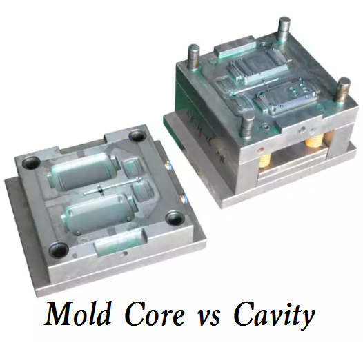
The core and cavity in the mold are different. The machining of the core is on the outer surface, and the processing of the cavity works on the inner surface. The material of the core and cavity shall have good polishing, wear resistance, corrosion resistance, and machinability.
Requirements of Mold Core and Cavity
1) High requirements for surface roughness. Due to the poor fluidity of plastic, the roughness of the formed surface is required to be R= 0.1-0.2µm,
Therefore, all surfaces of the working part should be ground and polished.
2) The position accuracy is required to be high. The working part and fixed part on the punch and core of the plastic mold meet the position accuracy requirements. At the same time, the coaxiality requirements shall be considered, and the above requirements shall be guaranteed in the processing technology.
3) Demoulding slope. The molding part of the plastic mold core and cavity shall have a demolding slope.
Quality Inspection Method of Mold Core
1. Wipe the depth micrometer clean before use, and then check whether its moving parts are flexible and reliable: the differential cylinder should rotate flexibly in the full stroke, the differential screw should move steadily, and the locking device should function reliably.
2. Select and replace the measuring rod according to the measured depth or height.
3. The 0-25mm depth micrometer can directly check the zero position: use the 00-level platform to clean the platform, the datum plane, and the measuring surface of the depth micrometer, and rotate the differential cylinder to make its end face fall outside the zero line of the fixed sleeve, then stick the datum plane of the micrometer on the working surface of the platform, press the base with the left hand, and slowly rotate the ratchet with the right hand, Check the zero position after the measuring surface contacts the working surface of the platform: the zero graduation line on the differential cylinder shall be aligned with the vertical graduation line on the fixed sleeve, and the end face of the cone surface of the differential cylinder shall be tangent to the zero graduation line of the sleeve.
4. For depth micrometers with a measuring range of more than 25 mm, the zero position shall be checked with a check gauge (which can be replaced by a gauge block): the working surfaces of the check gauge and the platform shall be wiped clean, the check gauge shall be placed on the platform, and the datum plane of the depth micrometer shall be stuck to the zero position of the check gauge.
5. When using a depth micrometer to measure blind holes and deep grooves, the hole and groove bottom are often invisible, so be careful when operating the depth micrometer and avoid using force recklessly.
6. When the diameter or slot width of the measured hole is larger than the base of the depth micrometer, an auxiliary positioning reference plate can be used for measurement.