The overflow exhaust system in the die casting die comprises an overflow groove and an exhaust groove. In order to improve the quality of die-casting parts, during the process of filling the cavity with molten metal, the gas in the cavity shall be excluded as much as possible, and the front-end condensed metal liquid mixed with gas and polluted by residual release agent and lubricant of the coating shall be excluded. Therefore, it is necessary to set an overflow exhaust system. The overflow exhaust system can make up for the casting defects caused by the unreasonable design of the gating system. Here we tell you how to accurately design the overflow groove and exhaust groove of die casting die.
Correctly understand overflow tank and exhaust tank
In the design of die-casting die, overflow groove, exhaust groove, ingate and runner are usually considered as a whole, but the purpose of setting overflow groove and exhaust groove of die-casting die is different:
The main function of the overflow tank is to push the condensed metal liquid at the front end to the outside of the mold cavity to achieve a good and orderly filling process;
The main function of the exhaust groove is to exhaust the air in the pressure chamber, runner and mold cavity and the gas from the lubricant from the mold, so that the gas is not trapped in the casting.
Two aspects shall be considered in the design of overflow tank:
The first is to consider the specific position of the overflow groove on the casting;
The second is to consider the volume of the overflow tank.
The former requires the mold designer to accurately control the flow direction of molten metal in the mold cavity, which is the prediction of the general direction. The latter requires the designer to accurately calculate the overflow amount of molten metal, otherwise the mold design will fail.
Common design faults of overflow tank:
First, the opening position of overflow tank is not reasonable;
Second, the estimation of overflow is inaccurate.
Even if the location design is reasonable, if the volume calculation value is small, it still cannot reach the expected goal. The overflow tank shall be designed at the last place where the molten metal reaches, and the overflow amount shall be considered at the same time. The calculated reasonable overflow amount can fully absorb the condensed molten metal and the contaminated molten metal at the front end.
The exhaust slot shall be designed at the appropriate position of the die-casting die, and the appropriate size shall be considered. The biggest problem of exhaust gas is that the inaccurate control of exhaust gas amount leads to a large amount of gas trapped in the mold.
Generally, at the beginning of the design of a set of die-casting die, the sprue system (ingate and runner) can quickly determine the approximate shape (ingate cross-sectional area, runner cross-sectional area and other parameters) through theoretical formula calculation. However, it is difficult to accurately and reasonably design the overflow trough. In addition, the exhaust trough is immediately behind the overflow trough, so the location of the exhaust trough becomes complicated.
Use simulation tools to obtain accurate design basis
In order to accurately obtain the design basis of the overflow tank, we can use the “multi gate filling” mode of the “intelligent casting super cloud” die casting simulation platform to preliminarily simulate the filling of the designed gate system, and the final filling position of the molten metal can be quickly found from the calculation results.
(the multi gate scheme is to quickly determine the approximate final filling area, so as to determine the approximate position of the overflow trough first, and finally determine the overflow trough position. It still needs a complete gating system to calculate and determine.)
Through the calculation of the “multi gate filling” mode, we can roughly obtain the approximate volume of the last filling area of the cavity corresponding to each gate (generally, the volume of the metal liquid that has not been filled when the cavity is filled to 90% or later). According to this volume, we can design an overflow tank with sufficient overflow volume close to the actual situation.
In this example, the calculated maximum spill is 40 grams. However, considering that there should be enough space for the front-end condensed metal liquid, we multiply the maximum overflow volume by a factor of 1.15-1.2, and finally determine the weight of each overflow tank to be 48g.
The casting is zoned to determine the location of overflow tank
In order to accurately calculate the exhaust volume, the exhaust groove of the die-casting die can be calculated and designed according to the following steps:
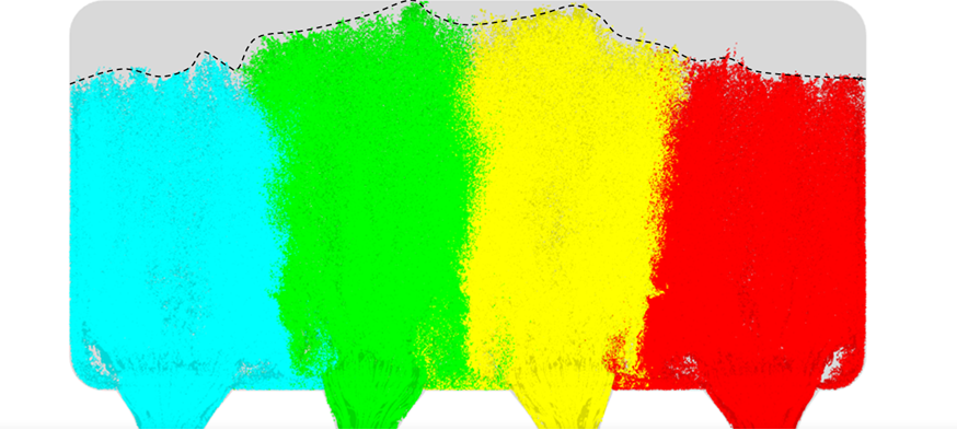
-The casting shall be partitioned, and the volume of each pouring section can be preliminarily determined by referring to the calculation results of “multi gate filling” mode;
-Calculate the flow of molten metal during cavity filling (the purpose is to determine the inner gate speed and rapid filling time), which can be calculated by theoretical calculation formula;
-Determine the cross-sectional area of the total exhaust groove with the exhaust speed not exceeding the sound speed (200m / S is selected this time).
After the partition is completed, set the position of the overflow port according to the estimated flow direction of the molten metal and the shape at the later stage of filling (filling to 90% and later), and then place the exhaust slot behind the overflow slot and between (adjacent) pouring partitions. Therefore, the exhaust area should be proportional to the average volume of the two pouring partitions. If the exhaust slot is located on one side of the casting, the exhaust area shall be proportional to half of the partition volume on that side. (after the metal liquid is fed from two adjacent gates, a residual cavity similar to “V” will be formed at the later stage of filling, and the gas discharge amount in this “V” shaped cavity is proportional to the cross-sectional area of the exhaust port, that is, the exhaust port set at this place shall be responsible for the gas discharge in two adjacent filling areas.)
Calculate the area of the exhaust duct according to the zoning
The following describes the specific calculation process of the size of the lower exhaust groove. This piece uses 1250 grams of aluminum, and requires a filling time of 0.058 seconds and an ingrate speed of 43 meters / second. The calculated flow rate was 7.94 liters per second (0.00794m ³/ s)。 The total ingrate area was calculated to be 185 square millimeters. According to the exhaust speed of 200 m / s.
If the depth of the exhaust slot is determined to be 0.4mm, the total width of the exhaust slot is 41.625/0.4 ≈ 104mm
Since the exhaust slot is located between the adjacent pouring sections of the casting, the size of each exhaust slot must be 50% of each pouring section After calculating and determining the exhaust groove area of each pouring area, modify the casting pouring system.
Verification of “smart casting super cloud”
After the overflow groove and exhaust groove are finally determined, the calculation is carried out again through the “intelligent casting super cloud” die casting simulation cloud platform.