Die Casting Runner Design Guide - Steps for How to Design the Die Casting Runner | Diecasting-mould
The runner of a mold is a passage connecting the sprue and the gate where molten metal enters the cavity, die casting runner design is important to determine the quality of die casting parts. A good runner design can make the filling process of liquid metal more stable, exhaust more smoothly, and obtain high-quality castings, also conducive to the die life.
Die Casting Runner Design Guide & Tips - Steps for How to Design the Die Casting Runner
When designing die casting runner, the following steps are often required.
1. Casting analysis
– Die casting material type and size: different alloys have different solid-liquid phase temperatures, fluidity, different performance in the flow process and solidification process. The size and weight of the casting directly determine the amount of metal, so the volume or weight of the casting is the most basic constraint parameter for the runner design.
– Wall thickness: wall thickness largely determines the distribution of hot spot, while the cooling speed of thin wall area is faster, which needs higher filling speed and shorter filling time, while the opposite is true for thick wall area. In addition, the area where the thickness changes abruptly is also the part where defects are easy to occur.
– Casting shape: the geometric shape of the casting affects the design of the runner. For example, the cylindrical part and the square box part require different designs. For the die casting parts with complex shapes, it is often necessary to arrange the inlets according to the geometric characteristics of different regions after the partition.
– Quality requirements: the quality requirements of castings include surface quality requirements, air tightness requirements, mechanical strength requirements, etc. these factors not only affect the design of die casting runner, but also determine many production factors such as die casting machine, production cycle, process parameters, etc.
2. Determine the entrance of molten metal and exhaust port
According to the first step of casting analysis, it is first determined where the liquid metal enters into the runner system and where the exhaust overflow groove is set. Generally speaking, the basic flow characteristics of castings are fixed after the entrance and exhaust port are determined. Generally speaking, some common design principles can be considered to determine the flow regime characteristics, such as:
– Shortest distance. The longer the distance is, the lower the temperature of the liquid metal is, the less fluidity is likely to occur, resulting in all kinds of fluidity defects.
– Thin wall preposition. Because of the fast cooling of the thin-walled area, if the thin-walled area is located at the end of the filling, it is easy to produce defects. Therefore, in general, it is recommended to take the thin-walled area as the front end of the process. If it has to be rear-mounted due to structural reasons, a half channel can be considered for flow and temperature supplement.
– Damping. Some casting structural characteristics will have a strong obstacle to the flow of liquid metal, such as deep shell casting, make deep molding area flow in the earlier stage, the flow speed is high, and can better fill the mold.
3. Calculate the maximum filling time and gate speed
Gate flow x filling time = casting volume, and casting volume is a fixed value, shorter filling time will inevitably require faster filling speed, which also has higher requirements for the machine. But if the liquid metal velocity is too high, it will bring erosion defects and affect the die life; If the speed is too low, it is easy to have the problem of insufficient liquidity and poor filling. Therefore, for the die casting, the filling time should be in a reasonable range to ensure that the casting is in a good casting space.
4. Casting divisions
When the gate speed, area, and filling time are determined, it is necessary to set the zone according to the casting flow characteristics. The casting is divided into several different areas, each corresponding to a gate. This has the advantage of ensuring smooth filling.
5. Calculate the amount of metal in each area
According to the volume of each zone determined in the previous step, determine the size of each corresponding gate, so as to ensure that the amount of liquid metal flowing into each gate can match the corresponding zone volume, and ensure that each strand of liquid metal can reach the exhaust position when filling completed, also avoid defects caused by flow imbalance to the greatest extent.
6. PQ diagram check
PQ diagram is a pressure flow diagram. After selecting parameters such as suitable tonnage of die casting machine, hammer diameter, and pressure chamber length, it must be checked through the PQ diagram to ensure that the current flow design can match the appropriate machine equipment. Only when the working point of the machine is within the reasonable working area of the PQ diagram and there is a large process margin, the next step of runner modeling design can be started.
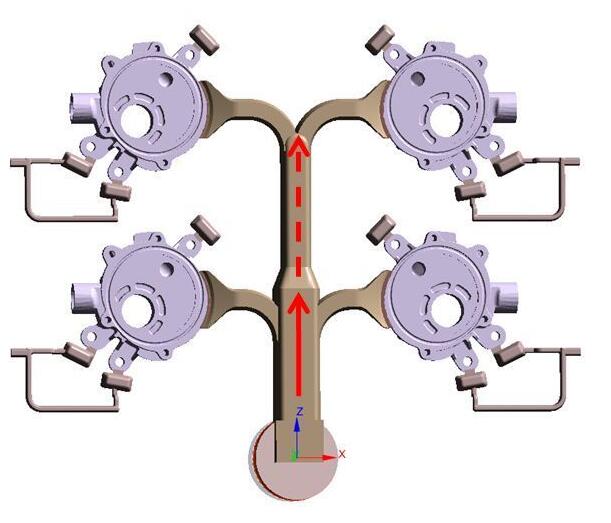
7. Create runner and exhaust
– Simultaneous arrival: the time of liquid metal arriving at each gate should be as consistent as possible. In order to achieve this goal, it is necessary to optimize the design of three branch channels. The flow distance of the middle branch channel is short, so the flow length can be increased.
– Cross-sectional area descending: the cross-sectional area of the runner must be gradually reduced with the flow direction, so as to ensure that the runner is always in a full state, and will not be involved in the air due to the increase of the runner.
– The cooling condition of the runner. The runner is usually designed to be flat, and the aspect ratio must meet a certain range. If the runner is too thick, it is easy to delay the solidification time of the runner, which affects the dimensional accuracy of the casting due to the shrinkage deformation of the runner. However, if the flow channel is too thin and the cooling speed is too fast, it is easy to cause the third phase pressure maintaining failure, and it is unable to transfer the pressure to the casting for feeding. The runner and overflow groove can also be used to balance the mold temperature, which is conducive to heat supplement for some thin-walled parts of the casting.
8. Simulation and comparison of multiple designs
In practical work, there are usually many kinds of runner schemes, which need to be simulated and compared to select the best one with the best process margin and the least risk of hole defects for subsequent trial production. The simulation can not only analyze the flow process and solidification process in advance, but also analyze the stress and deformation, casting mechanical properties, etc. in the design stage, it can consider the quality control in the later stage, and help the design idea of poor filtration.
9. Runner adjustment and optimization
After the design is determined, it may be necessary to optimize the runner design, such as adjusting the gate of a branch runner to change the flow rate, or adjusting the injection angle to improve the local flow pattern, etc. It should be noted that any change of runner and gate should not affect the process parameters determined in the earlier stage.