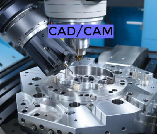
The mold industry is one of the foundations of industrial development, and CAD/CAM technology is an important technical equipment in the production of the mold industry. It is a core technology of high value-added manufacturing technology, and also a golden field of integration of automation and informatization. The level of its technology is an important symbol of the modernization level of the country’s industry. It is the further optimization of mold design products by engineering and technical personnel using computers. This article elaborates on the current application status of CAD/CAM technology in modern mold production through its application in cold stamping dies, forging dies, plastic molds, and die-casting molds.
1 – The Application of CAD/CAM Technology in Cold Stamping Dies
Cold stamping die CAD and CAM systems generally include five modules: system work management, process analysis, mold structure design analysis, graphic system and engineering database. The main content includes: importing original drawings and data; Process setting and analysis of parts; Determine the plan; Scientific calculation and selection of press machines; Mold structure design and graphic processing; Export the corresponding CNC machining program; Output process files. Complete other related tasks.
In the last century, CAD/CAM technology was used in the design and manufacturing of molds for automotive panels, achieving good economic results. Toyota Motor Corporation of Japan was the first to apply it to the design and manufacturing of molds for automotive panels. The company also utilizes a CAD/CAM system for automotive panels, which includes NTDFB and CADERIT design software, as well as TINCA software for processing convex and concave molds, to design the exterior shape, structure, die CAD, main model and die manufacturing, and fixture processing. According to reports, due to the implementation of the system, the design and manufacturing cycle of Toyota’s automotive panel forming die has been reduced by about 50%. Foreign countries have also developed specialized modules for automotive panel mold design on the UG-II software platform, such as sheet metal part design, body design, cover stamping process design, and mold structure design.
In the late 1960s, research began on progressive die CAD/CAM, and by the 1970s, it had been preliminarily applied. The early main functions were strip layout, die layout, process calculation, and NC programming, which were only used for simple stamping progressive dies with two-dimensional graphics. In the 1990s, internationally renowned technologies such as Pro/E, UG-II, CADD5, Solidworks, MDT, etc. were gradually applied in the mold industry. And gradually, specialized modules for forming technology and mold structure design are introduced in modules such as metal part modeling, blank unfolding, blank layout, mold design, and CNC machining. In the 1980s, Shanghai Jiao Tong University and Xi’an Jiao Tong University successively carried out research and development of progressive die CAD/CAM systems in China. Huazhong University of Science and Technology has collaborated with UGS Corporation in the United States to develop the progressive die CAD/CAM software NX-PDW, which has the function of automated design and was put into commercial use in 2003.
The application of CAD/CAM technology in automotive panel molds and progressive molds, as well as the development and application of CAD/CAM software, play an important role in the production of cold stamping molds. It plays an extremely important role in shortening the entire processing process, optimizing the structure of cold stamping molds, and improving the production efficiency of molds. Nowadays, many research institutions have also begun to conduct research in this area and have achieved certain results. For example, using UG/API, GRIP, and VC++to simplify the CNC programming of automotive panel molds, bringing classes and objects into parameter definitions, and establishing an intelligent automotive panel mold and progressive mold system.
2 – The Application of CAD/CAM Technology in Forging Dies
In the 1970s, extensive research on the application of CAD/CAM technology in forging dies began both domestically and internationally, achieving good results in process design, structural design, and dynamic simulation. Most people develop forging die CAD/CAM systems based on axisymmetric forging dies, as the geometric shape of symmetric forgings is simple, easy to describe and define, while CAD/CAM systems for long axis forging dies are difficult and have low universality, Its design is much more complex than axisymmetric forging dies [21. The axisymmetric forging die CAD/CAM system consists of three design modules: forgings, forging process, and forging die structure, as well as an NC programming module. Forging design mainly involves designing cold forging drawings and hot forging drawings, including the selection of parting surfaces, supplementation of machining allowances, addition of rounded corners, and design of draft angles. Forging process design is to determine whether to use preforming process, how to use it, and how to choose the tonnage of forging equipment s] . The development direction of forging die CAD/CAM systems is to further develop and execute towards standardization and die standardization technology, and to deeply apply it in industrial technology and artificial intelligence technology.
3 – The Application of CAD/CAM in Plastic Molds
According to different molding methods, plastic molds are divided into injection molds, compression molds, hollow blow molding molds, etc. Among them, injection molds are the most widely used. CAD/CAM technology for injection molds mainly provides strong assistance to technical personnel in two aspects: first, scientific calculation and dynamic simulation of molds through CAE technology; The second is to optimize the CAD design, simulation, and graphic processing of the injection mold structure. The main contents of injection mold CAD/CAM include:
- Establish a geometric model.
- Mold cavity design.
- Design of mold structure scheme.
- Selection of standard mold bases.
- Graphics processing.
- Generate CNC machining programs for molds.
- CNC machining.
4 – Application of CAD/CAM technology in Die Casting Molds
Die casting die CAD refers to the work completed using computer technology in the process of information retrieval, scheme conception, analysis, calculation, engineering drawing, and document compilation of die casting technology and die casting mold design. Design in CAD encompasses many disciplines, and the use of computer-aided analysis, calculation, and engineering drawing is an activity in the design process.
The main content of computer-aided design for die-casting molds is to perform scientific calculations based on geometric model features and alloy types; Choose a suitable die-casting machine and material; Mold structure design (mainly the design of pouring system, cavity inserts, guiding mechanism, template, and ejection mechanism); Finally, draw the mold drawing.
A typical 3D die-casting mold CAD system mainly includes the following modules:
- Calculation of process parameters for die-casting parts.
- Parameter selection of die-casting machine.
- Design of pouring system.
- Design of parting surface.
- Design of mold structure.
- Design the launch mechanism.
The commonly referred to die-casting mold CAM mainly includes mold machining process design, CNC programming, and simulation of CNC machining process. CAM mainly selects tasks such as machine tool types, machining path formulation, and simulation machining. Numerical control technology is the most core technology in CAM. CNC machining mainly includes: generating CNC programs; CNC machining process. For example, the expert system for die-casting mold design developed by Toyota in Japan is based on a database of design standards and technical information. According to part drawings, the system designs the structure, sketch, cavity, process, assembly drawing, structure, machining path, simulates and simulates machining into CNC programs, CNC machining processes, etc.